By Roger E. Blanton, P.E., Sales Manager, Howden Roots
03/20/2017
Pneumatic conveying systems are widely used in manufacturing plants and process industries. They provide a practical method of bulk-solid material transport. A surprisingly wide variety of powders and granular material can be effectively moved from one location to another within the plant. “Compared with other bulk-solid transport systems, a properly designed pneumatic conveying system affords many advantages, including: flexible pipeline routing, multiple pick-up points (as in vacuum systems), and delivery points (as in pressure systems), little to no cross-contamination, dust free operation, and an inert atmosphere.”(1)
|
|
 Roger E. Blanton, P.E., Howden Roots
The heart of the pneumatic conveying system (air mover, solids feeder, pipeline, and separator) is the air mover. Correctly specifying the volumetric flow rate and pressure levels required to move the material will determine system reliability. One must also look at pipe size, distance, and the weight of the material being moved. A company specializing in the design requirements of pneumatic conveying systems is best consulted for evaluating these requirements and specifying the required air or gas flow rate for the system.
Using a high-pressure source, such as plant compressed air, wastes valuable energy. Howden Roots positive displacement (PD) blowers provide a cost effective, efficient solution. They are used extensively in dilute phase applications where the bulk material is conveyed through the pipeline in suspension, and the required pressure does not exceed 15 PSIG. Not all, but several Howden Roots blowers are bi-rotational so they can be used for vacuum or pressure service.
The operating principle of a conventional Roots type blower is quite simple. The reader is directed to previous articles where this is explained in detail, and not repeated here.(2,3) It’s important to note that Roots blowers do not create internal pressure or vacuum, they simply overcome system losses.
PD Blower System Design and Capacity Control
Selecting the correct blower is the most important decision when designing a pneumatic conveying system. The rating of the blower is expressed in terms of required pressure and volumetric flow. Any miscalculation in specifying the above will result in a conveying system that is oversized, isn’t capable of achieving the material flow rate required, or experiences pipeline blockage. Blockage occurs where the dynamic air or gas pressure in the system is at its minimum value. The volumetric flow rate from the blower depends on the diameter of the pipe being used and the velocity required to convey the specified material. For design purposes, standard conditions (68°F, 14.7 psia, 36% RH, 0.075 lbs.ft3)(4) are typically used in specifying the blower.
Capacity control of PD blowers is limited because the blower is cooled by the mass flow through the machine. Throttling the blower will result in overheating. Effective methods of capacity control include,
- Staging blowers off or on in systems where multiple blowers are used in parallel to attain required flow
- Using a Variable Frequency Drive (VFD) on the blower motor to adjust blower speed within defined limits
- Using a Blow Off Valve (BOV) in the blower discharge piping
- Changing the sheave sizes on belt driven blowers.
PD Blower Limitations
Inherent by their design, a PD blower has both mechanical and thermal limitations because the impellers are machined to close tolerances and the clearances are very small. Therefore, PD blowers have speed, temperature and pressure limitations that must be considered when sizing a pneumatic conveying system. As a general rule, PD blowers have the capability to turndown to roughly 50% of the maximum design speed because temperature rise increases as unit speed decreases, as discussed above. In addition, gear tip speed must be maintained at a minimum of 1,000 FPM and a maximum of approximately 4,700 FPM (varies by model) - which is critical for proper lubrication. Blowers are generally limited to a maximum average temperature rise of 250°F (121°C) because of issues with thermal growth. Lastly, Roots blowers are limited to a 2:1 compression ratio because as pressure increases there is a corresponding increase in discharge temperature.
Basic Pneumatic Conveying System Calculations
Blower manufacturers do not routinely size pneumatic conveying systems, leaving that task to specialized design companies. However, it is helpful to have some basic understanding of the procedure. Preliminary design of power, air requirements, and pipe size can be developed, but experienced designers add their own unique guidelines compatible with their equipment. The material to be conveyed and the distance required to move the material limit pneumatic conveying systems.
Saturation (S) is defined as the cubic feet of air required to move or convey one pound of a given material for a specified distance. Tables of this value (S), pressure factor (PF), pipe velocity (v), and the horsepower required to convey one ton of material per hour (HP) have been published.(5) Once the desired total flow rate of the product and distance involved is determined, and the material is defined, a simple procedure can be followed to preliminarily size the pneumatic conveying system components.(5)
A Sample Calculation Sequence (for illustrative purposes only)(5)
- Determine the Saturation (S), hp/ton (HP), pipe velocity (v), and Pressure Factor (PF) values for the conveyed product from the published saturation table.
- Calculate the volume of free air (Qs) required: Qs (scfm) = S X conveying rate (lb/min)
- Calculate the required operating pressure (P, psig): P = HP/S X PF
- Calculate the actual cubic feet per minute (acfm) at the feed point (site elevation = 0 feet asl): acfm = scfm X 14.7 / (14.7 + P)
- Calculate required pipe area (A): A = acfm / v
- Calculate rotary feeder leakage (L) in acfm: L = feeder volumetric displacement X feeder rpm X 1.3
- Calculate feeder leakage in scfm (Ls): Ls = L X (14.7 + P) / 14.7
- Calculate total air required by the blower (Q): Q = Qs + Ls
- Calculate required blower speed (Sb), rpm: Sb = Qs / blower displacement (cubic feet per revolution, cfr) + slip (rpm) [cfr & slip from blower manufacturer]
- Calculate required blower horsepower (HP): HP = Sb X cfr X P X 0.005
|
Howden Roots PD Blowers for Pneumatic Conveying Howden Roots has several blower models suitable for pneumatic conveying applications. A few are shown in the following pictures and descriptions. |
|
|
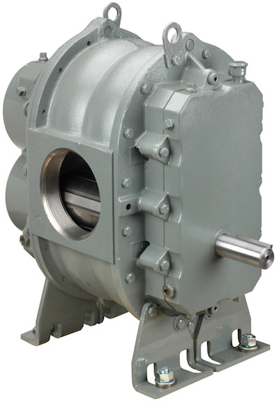
URAI DSL (2” – 7” gear size) The Roots Universal RAI DSL (Dual Splash Lubricated) heavy-duty rotary blowers are designed with detachable, rugged steel mounting feet that permit easy, in-field adaptability to vertical or horizontal installation requirements. Because of the detachable mounting feet, these units can be easily adapted to any of four drive shaft positions: right, left, bottom, or top. The compact, sturdy design is engineered for continuous service when operated in accordance with speed and pressure ratings. |
 |
|
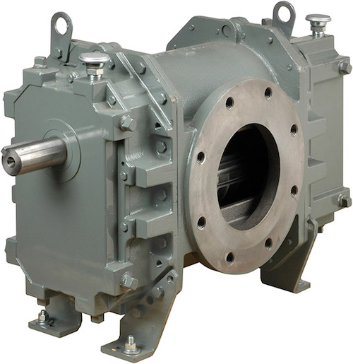
RAM™ (4” – 6” gear size) RAM™ stands for Reliability, Availability, and Maintainability. Today, more than ever, Howden Roots is committed to supplying our customers with reliable products manufactured with state-of-the-art CNC machine tools. Production and inventory are being scheduled and controlled to ensure these units will be available when you need them. Design improvements such as repositionable rugged steel mounting feet and die-cast aluminum drive end covers and gear covers help to reduce installation costs and make normal maintenance easier. |
 |
|
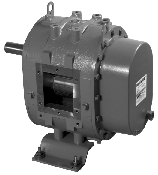
ROOTS-FLO® (4” gear size) ROOTS-FLO® rotary positive displacement blowers are heavy-duty rotary units in a compact, sturdy design engineered for reliable pneumatic conveying of grain and similar products. |
 |
For more information please contact Roger Blanton, P.E., Howden Roots, at email:roger.blanton@howden.com or visit www.howden.com.
To read similar articles on Pneumatic Conveying, please visit www.blowervacuumbestpractices.com/industries/conveying.
About the Author:
Roger E. Blanton, P.E. is currently a Sales Manager for Howden Roots LLC based in Tulsa, Oklahoma USA. He is a registered professional engineer working for over 35 years with rotating equipment and petrochemical processes. Blanton holds a BS degree in Mechanical Engineering from the University of Tulsa, and an MBA degree from Oklahoma State University. He has specialized for the last 25 years in technical product design, application, and sales; new product development and introduction; sales and distribution management; and international business development. He is a member of the American Society of Mechanical Engineers (ASME), Tau Beta Pi Engineering Honor Society, and past president of the Greater Ozarks International Trade Association.
END NOTES
- Maynard, Eric, “Designing Pneumatic Conveying Systems”, CEP Magazine, May 2006, pg. 23-31.
- Blanton, Roger E., “Maintenance & Operation Guidelines for Rotary Lobe Blowers in Petrochemical Applications”, Presented at the 50th Annual Chem Show Conference, November 20, 2003, Javits Convention Center, New York City, NY. (copy available from author upon request)
- Blanton, Roger E., “Get the Most Out of Your Rotary Lobe Blower”, Chemical Engineering, vol. 109 no. 7, July 2002, pg. 77-80.
- “SCFM vs ACFM Are you really getting the blower performance you’re specifying?”, Dresser Industries, Inc. Roots Division, 1988, Houston, TX.
- Stoess, H.A. Jr., Pneumatic Conveying, John Wiley & Sons, 1970.