By Tom Jenkins, JenTech Inc.
06/23/2017
The capacity and pressure requirements of blowers in a Water Resource Recovery Facility (WRRF) are determined by the aeration system. When systems are manually controlled blowers often operate at constant flow and pressure day in, day out. When the aeration system is automatically controlled to maintain a set dissolved oxygen (DO), however, the blower’s flow and system pressure vary constantly. Understanding these variations will help designers and suppliers optimize blower performance.
Aeration Dictates Flow Rates
In a WRRF the blowers are designed to meet worst case loads. The biochemical oxygen demand (BOD) is the primary factor determining the necessary air flow rate.
The aeration basin wastewater contains dissolved and particulate pollutants. The pollutants are primarily organic (carbonaceous) compounds and ammonia (NH3). Clumps of microorganisms, referred to as floc particles, metabolize the organic compounds and convert the ammonia to nitrate (NO3). To accomplish these processes, they utilize oxygen dissolved in the mixed liquor. Byproducts of the biological activity, water and carbon dioxide, are released into the mixed liquor. [See Figure 1.]
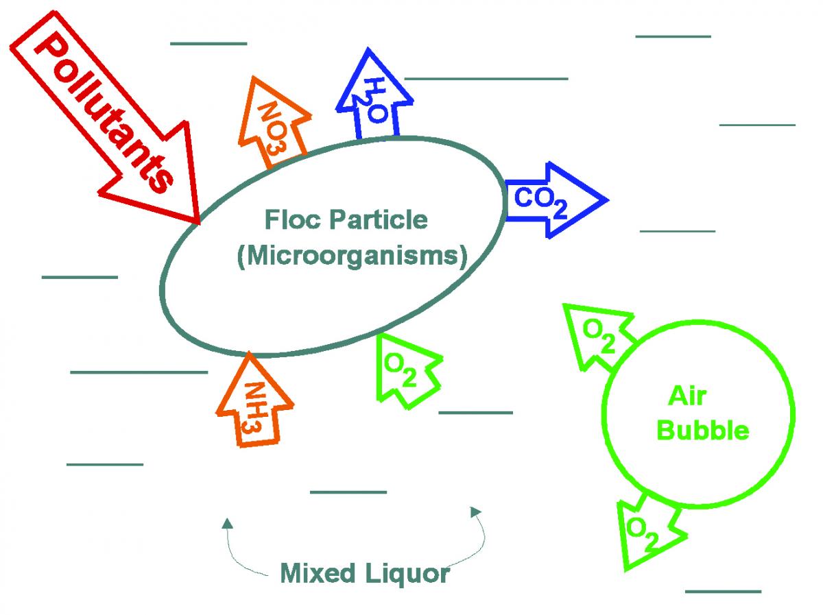
Figure 1: The Biological Process in Aeration Basins
In most WRRFs the dissolved oxygen originates in air bubbles introduced in the bottom of the aeration basin by diffusers. The air is delivered to diffusers by blowers. Approximately 1.1 pounds of oxygen is required to metabolize 1.0 pound of BOD, and 4.6 pounds of oxygen is required to convert 1.0 pound of NH3 to NO3. The oxygen needed by the process can be converted to a mass flow rate of air.
The air flow rate for wastewater applications is often expressed as SCFM (Standard Cubic Feet per Minute). This appears to be a volumetric flow rate, but the defined standard conditions establish a fixed density, and therefore it is effectively a mass flow rate. In the wastewater industry standard conditions are 68 °F, 14.7 psia, and 36% relative humidity, resulting in a density of 0.075 lb/ft3. Air is 21% oxygen by weight, establishing the mass of oxygen delivered in each SCFM.
Some air flow meters measure mass flow and others measure volumetric flow. The two types may be mixed in a single DO control system. This is not an issue with feedback based DO control – the system simply adjusts the blowers and aeration basins until the DO concentration reaches setpoint.
Another complicating factor is that blowers are volumetric devices. Blower manufacturers prefer to work in ICFM (Inlet Cubic Feet per Minute), the volumetric flow at the blower inlet connection. Another term used is ACFM (Actual Cubic Feet per Minute). It is important to always define the temperature and pressure of the volumetric flow rate under consideration to avoid errors.
It is possible to convert between standard conditions and actual conditions:
![]()
Where:
ACFM = Actual volumetric flow rate, ft3/min
SCFM = Flow rate at standard conditions, ft3/min
Ta = Actual air temperature, °R
pa = Actual air pressure, psia
This formula ignores relative humidity. For most process calculations the resulting error is negligible.
The process demand for oxygen varies widely in most municipal WRRFs. Rain events, industrial loads, and internal process sidestreams impact the biological oxygen needed. The most common variation is the result of daily (diurnal) fluctuations in wastewater flow to the plant as population activity varies during the day. [See Figure 2.]
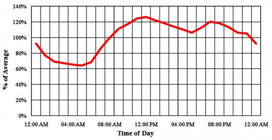
Figure 2: Typical WRRF Diurnal Flow Variations
A DO control system modulates blower air flow rate to match process demand. The designer’s selection of modulation technique is based on blower type and economics. Dynamic (centrifugal) blowers may be modulated by throttling, inlet and discharge guide vanes, or variable frequency drives (VFDs). VFD control is the most energy efficient method for dynamic blowers. Positive displacement (PD) blowers must be modulated by variable speed usually by using VFDs.
Other Air Demands
The typical WRRF has other processes using air. In some cases, these other processes will increase both the total air requirement and the variability needed to match blower output to the process.
Post-aeration is used to elevate the DO of the plant effluent prior to discharge to the receiving water.
In many facilities aerobic digesters are used to reduce the volume of sludge (microorganisms from the aeration process) prior to disposal or beneficial use. Aerobic digesters do not operate continuously. Periodic removal of excess water from the digesters results in changing water depth. Aerobic digestion increases the total blower flow rate requirements.
Some plants use an equalization (EQ) basin to decrease the impact of load changes from diurnal flow variations and rain events . The basins are aerated to avoid septicity and odors. The water level in an EQ basin fluctuates. This changes both the required air flow and the backpressure.
Most WRRFs use open channels to distribute the wastewater to various processes. It is necessary to aerate these channels to avoid odors and eliminate solids settling. The depth of the channels is typically much lower than the depth of the aeration basins. This means that the channel’s air pressure is lower.
Many facilities have a single set of blowers discharging into a common air header. The various processes all tap air from this header. This raises the pressure of the total air flow to match the highest pressure. Excess pressure is reduced by throttling the air flow to other processes. It may be more cost effective to use separate blowers for processes, such as channel aeration and digestion, that have low or variable pressure requirements. The additional equipment cost is recovered through lower energy cost.
Pressure Requirements
Blower discharge pressure has as much impact on blower power as flow rate. A DO control system can have an impact on discharge pressure. Pressure considerations need to be included in equipment selection. Note that blowers do not actually produce pressure. Blowers produce air flow, and the system resistance to flow creates pressure.
For most aeration processes the largest single component of the discharge pressure is the submergence of the diffusers in the wastewater. This results in static pressure that must be overcome before any air flow can occur. Static pressure is typically 80% to 90% of total discharge pressure. The second factor in system pressure is the friction loss resulting from air moving through pipe, fittings, valves, and diffusers. This friction loss is proportional to the square of the flow rate.
The combined total pressure can be calculated and plotted against the flow rate, creating the system curve:
![]()
Where:
ptotal = Total discharge pressure, psig
d = Depth of water at top of diffuser, ft
kf = Constant of proportionality for friction, psi/SCFM2
Q = Air flow rate, SCFM
If an operating point of flow and pressure is known, either from calculation or measurement, the constant kf can be calculated:
![]()
Where:
Pactual = Measured or calculated discharge pressure, psig
Qactual = Measured or calculated air flow rate, SCFM
DO control systems often employ throttling valves at the aeration basins to control the proportion of total flow that each basin receives. This results in a family of system curves as the system restriction increases with increased throttling of the basin flow control valves. In effect the value of kf varies with valve position. [See Figure 3.] For dynamic blowers, unless the blower is modulated to compensate for pressure changes, the total delivered air flow will be reduced as the pressure increases. The intersection of the blower performance curve with the system curve identifies the actual operating point as throttling fluctuates. The blower system must be designed to accommodate worst case throttling conditions, although in normal operation pressure should be lower than the maximum.
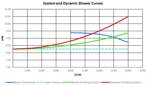
Figure 3: System Curve
For positive displacement blowers the performance “curve” is approximately a vertical line. The total blower air flow delivered to the system will not change when basin valves are throttled, but power consumption will increase with increased throttling.
Constant Pressure and Most-Open-Valve Control
In older DO control systems the blowers were operated at constant pressure. This was done to minimize the impact of one basin’s throttling on adjacent basins. Maintaining constant pressure was employed so blowers would modulate in response to throttling the basin valves. Constant pressure operation unfortunately resulted in increased power consumption, since excess pressure was created by the blowers and then lost in throttling.
As energy cost rose and control capabilities improved, techniques were developed to minimize parasitic pressure losses from basin valve throttling. These techniques are collectively known as Most-Open-Valve (MOV) control. Early MOV controls operated by altering the blower pressure setpoint when basin valves approached limits of travel. Current MOV logic uses advanced control capabilities to directly coordinate blower and basin air flow and valve positions to minimize pressure losses.
Limiting Factors
The flow and pressure delivered by the blower system cannot be infinitely varied to match changing process demand. There are limitations on blowers, aeration equipment, and the process that constrain the useable operating range. In most DO control systems a master control panel clamps the flow and pressure to stay within these constraints.
Pressure limits are generally a function of blower configuration. If dynamic blowers experience excess flow restriction, resulting in low flow and high discharge pressure, they experience damaging pulsating flow, called surge. Excess pressure on PD blowers will result in motor overload or damage to bearings and rotors.
High flow rates can cause motor overload for both dynamic and PD blowers. Low flow demand can also be a problem – most blowers are limited to a minimum of about 50% of design flow. If the DO control tries to operate the blowers below minimum overheating of blower or motor may result. The DO control’s master control panel should coordinate starting and stopping multiple blowers as required to maintain operation within safe limits.
The diffusers that introduce air into the bottom of the aeration tank also have a fixed operating range. If the flow is too low, air isn’t released uniformly across the face of the diffuser. This allows biological fouling to partially block the diffusers. If the air flow is too high the resulting pressure differential across diffuser membranes can cause physical damage.
The process itself has a minimum air flow rate, the result of needing to keep floc particles suspended in the wastewater. This mixing air flow is typically between 0.08 and 0.12 SCFM per square foot of water surface.
Conclusion
The aeration basins constitute the most critical use of air in most WRRFs. Automatic DO control modulates the blower system output to match biological demand for oxygen. Other aerated processes can increase total blower air flow requirements. The DO control system should also limit air flow and the resulting pressure to stay within the safe operating ranges. Including these factors in system design is necessary for optimizing aeration systems.
For more information contact Tom Jenkins, President, JenTech Inc. at email: info@jentechinc.com or visit www.jentechinc.com. Mr. Jenkins has texts now available in hardcopy and electronic versions titled Aeration Control and Facility Design at www.wiley.com and www.e-wef.org/store.
To read similar Aeration Blower System Assessment articles please visit blowervacuumbestpractices.com/system-assessments/blower-controls.
Watch the webinar recording Blower Demands with DO Control presented by Tom Jenkins.