In many manufacturing operations, a very significant compressed air use is pneumatic conveying of many types of materials such as cement, fly ash, starch, sugar, salt, sand, plastic pellets, oats, feeds, etc. Often these are systems that use high-pressure air (100 psig class) reduced to lower pressures (15 psig, 45 psig). This creates an air savings opportunity.
These processes are often complex and engineered by the manufacturer to utilize high-pressure inlet air. To convert them to low pressure may sometimes be a daunting job requiring significant changes in controls, valves, piping, regulators, orifices, etc., so plants are often resistant to approach these opportunities as a serious project.
Our area of expertise does not lie in the design, application, selection or operation of pneumatic conveying equipment. It does lie in the area of identifying the operating cost of compressed air as an energy source and opportunities to reduce plant operating cost by effective management of compressed air power.

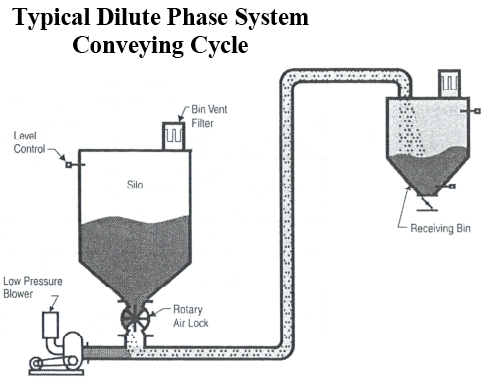
Dilute Phase Systems
The chart at left graphically shows the magnitude of opportunity that exists in electrical energy savings with compressed air produced at the appropriate lower operating pressure instead of using high-pressure air volume (scfm) reduced to a significantly lower pressure (psig).
The two most distinct categories of pneumatic conveying are low-pressure or high-pressure systems (there are other names “in between” such as medium phase, lean phase, positive pressure, etc.). The first category is low-pressure systems, also referred to as dilute phase pneumatic conveying systems. These systems utilize entry air pressure under 15 psig and use either positive or negative pressure to push or pull materials through the conveying line at relatively high velocities and volume. They are described as low pressure/high velocity systems and have a high air-to-material ratio.
A typical low-pressure system using a rotary air lock feeder will use a high pick-up velocity of around 2,500 fpm at the beginning of the system, and about 6,000 fpm at the end. The conveying line pressure is under 15 psig at the beginning and near atmospheric pressure at the end.
Low-pressure systems should use a low-pressure positive displacement blower as the primary compressed air source. Often, the abrasive nature of product being transported precludes the use of dilute phase and the associated very high velocities, which will create significant system piping and valve erosion.
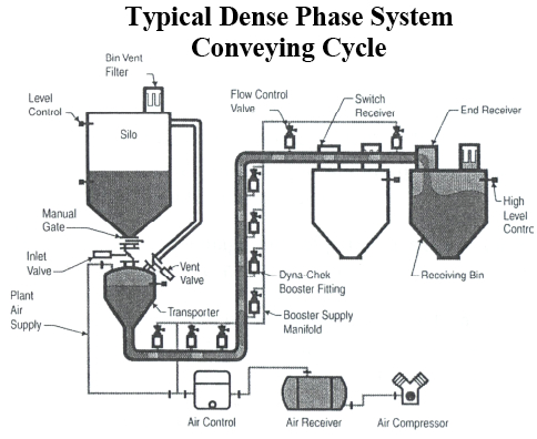
Dense Phase Systems
The second category, high pressure systems, are known as dense phase systems. These systems utilize air pressure above 15 psig (up to 50 psig) in the pipe and use positive pressure to push materials through the conveying line at relatively low velocities (from 100 fpm to a maximum of 1000 fpm) much like extruding. They are described as high pressure/low velocity systems and have a low air-to-material ratio.
Dense phase conveying uses smaller amounts of air to move large amounts of bulk solid material in slugs through the conveying line.
Generally the product being transported is often abrasive in nature. The Dense Phase system is selected to eliminate or minimize transfer pipe erosion, by maintaining the design’s moderate velocities and still deliver the appropriate pounds per hour of production. Generally, this type system requires an air compressor of the appropriate size and pressure (35 – 100 psig)
Dense phase conveying systems, if not already utilizing a dedicated lower pressure air supply, maybe able to be taken off the high pressure systems and an appropriate single-stage reciprocating rotary screw or centrifugal (single or two-stage) compressor can be dedicated to this scenario. The electrical energy cost per scfm of this air will be much lower than the high pressure and the unit can easily be shut off when not in use.
These flow volumes will vary greatly depending on product and the system design, but they will always be lower than a similar dilute phase system. Often these systems will have small booster pulsers along the transport path, which will add to the demand.
To evaluate the magnitude of potential savings once the required volume (scfm) is known, refer to Table 7.
When setting up a new conveying system, be aware of these opportunities to be sure your supplier and/or your consultant consider the true cost of air in basic designs.
Operating Air Fluidizers
The Dense Phase pneumatic conveying systems, particularly dense phase, use “booster pulsers” also know as “air saver boosters“or “air fluidizers” to help move the product along the line and free it from the piping walls. Multiple controls or fluidizers are typically installed through the wall of the hopper section and the wall of specific pipe runs to loosen the material and direct the air flow. Operating properly they input short small shots of air, as required, to control the natural solidity of the product column and maintain appropriate compressed air pipeline velocity. The “air saver boosters” are usually carefully set and controlled to optimize the expensive high pressure air and not destroy the product column solid integrity.
These fluidizers are usually one of two types:
• Air blow only with separate vibrator
• Air blow with built-in vibrator.
Here are some key tips to keep in mind when operating air fluidizers in your pneumatic conveying systems:
• Compressed air is your most expensive utility. If more air will not improve performance. Identify and control the minimum volume of air to do the job correctly.
• Run the air only when the vessel is discharging. This not only will minimize the use of air, but also will probably improve performance. Running the fluidizers when the discharge is closed may create voids in the material. When the discharge outlet opens, the material may flow into the void rather than out smoothly.
• Try to run all multiple fluidizers sequentially, not simultaneously. This will significantly reduce the demand impact on the air system and help to hold the product together.
• Take the time to design the best possible timing of the pulsers. Get the discharge performance you need with the shortest possible pulse time and longest possible interval. If you convey different products, establish optimum timed pulse aeration for each product and adjust accordingly.
• Run electric-operated vibrators whenever conditions allow. If you have to run air-operated vibrators, be sure they only run when needed.
A Case Study
This case study is of an older material transport system which shows some of the pitfalls in running a system without the proper controls.
The pneumatic transport system fills the eight supply silos with the appropriate material to be mixed and sent on to the furnace for production. Gravity feeds the material from the Blend Hold Hopper in the basement. The products are than pneumatically transported to two separate “Blender Hoppers” through 8” lines. These are for the two production lines. From the Blender Hopper, the mixed batch is pneumatically transported to three “Day Bins” for each line and then on to the furnace as required through 8” lines.

At the current production levels, the batch transporter system needs to constantly handle 30,000 pounds per hour of mixture. In order to establish a 2 hour cushion of supply in the Day Bins, the system must be capable of runs of 90,000 pounds per hour.
Over the years, in order to reach these continually increasing required transport levels, the basic system has been “adjusted”, particularly the air savers or boosters. These boosters are all running open with feed pressures from 30 psig to 90 psig as adjusted.
Today, the measured average flow through the transport system is 1,500 scfm average (velocity up to 1,200 ft/min) and sustained peaks of 2,600 scfm (velocity 2,000 ft/min) for 2-3 minutes – 2,000 scfm for 6-8 minutes. These peak surge demands appear to occur at 10-45 minute intervals with five to six similar events during each hour.

The deep drops in pressure are caused by a lack of available compressed air at the time from the effects of the somewhat convoluted interconnecting pipe and the response time of the control system. The plant is experiencing significant pipeline erosion.
The transport system appears to be now consuming 1,500 average scfm with peaks to 2,600 scfm.
If the transport system can be run with a 55 to 60 psia main air supply to the transport pipe there is a 112 kW average reduction in Primary compressed air input power and or electrical energy. At $0.10 kWh for 8500 hours per year, this would reduce the electric bill almost $95,200 per year annual electrical energy savings.
In order to implement all piping, valving, etc, must be checked to see if they can still perform at this lower input pressure. At lower pressure the piping may have to be bigger to avoid excess pressure drop. The air boosters if required could be tied to the high pressure system, but they would have to be carefully controlled. It would be best if they can be fed from the low pressure system with proper piping and regulation.
Vacuum Conveying
Vacuum pneumatic conveying has some inherent advantages compared to positive pressure pneumatic conveying:
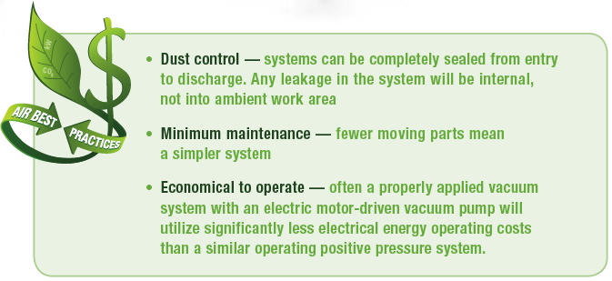
As is always the case, each proposed process should be evaluated with total annual electrical energy operating cost as a key ingredient in the selection process.
Although vacuum is most often used in dilute phase transport, it can also be used in dense phase system when economics and conditions dictate. Careful evaluation should be implemented to the optimal power drives particularly if a compressed air-driven central vacuum pump is planned to be used.
With a vacuum conveying system, an electric motor driven central vacuum pump should always be used from an energy efficiency standpoint. An air driven central vacuum pump starts out already “deep in the hole” with regard to energy efficiency.
For more information contact Hank Van Ormer, tel: 740-862-4112, www.airpowerusainc.com.