Introduction
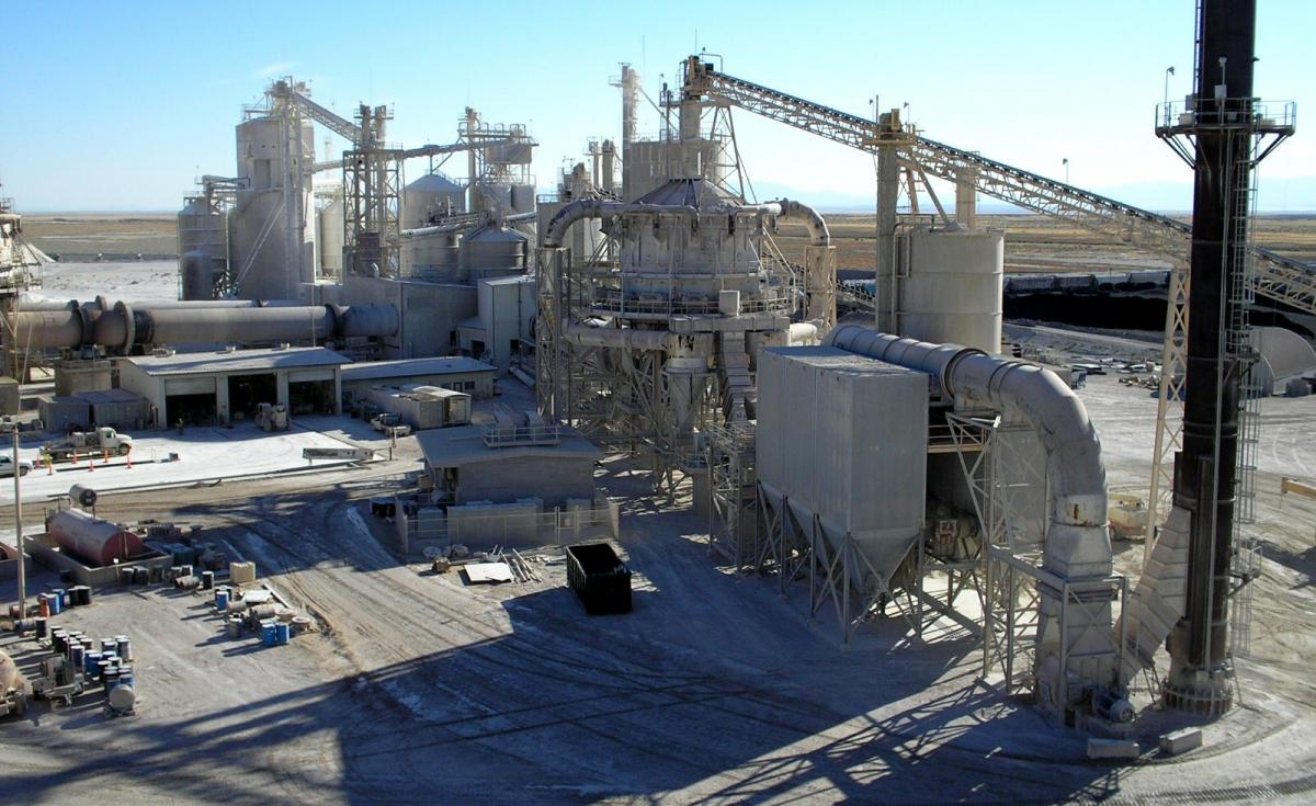
In thermal power stations, nuclear plants, and chemical and industrial plants, different types of bulk materials are used. The materials exist in different forms including lump, powder, granules, chips, and pallets. These bulk materials, in their different forms, require efficient and reliable material handling systems.
Here is a list of some commonly found bulk materials.
• Coal and coal ash are the materials found in thermal power plants.
• PET chips and nylon chips are commonly found in industrial plants.
• Sugar, flour, and chocolate powder are commonly found in food processing plants like chocolate plants.
• Zircon, zirconium hydro-oxide are found in nuclear power plants.
Belt conveyors, screw conveyors, and bucket elevators, are some of the conventional modes of transporting and conveying these materials. Specific materials, however, may require conveying in an enclosed form. Also, with layout constraints, it is preferred to convey materials in pipes using pneumatic systems.
This article describes Vacuum-type and Pressure-type pneumatic conveying systems. The pressure–type systems are broken down into Lean-phase and Dense-phase pneumatic conveying systems.
Vaccum Type Conveying System
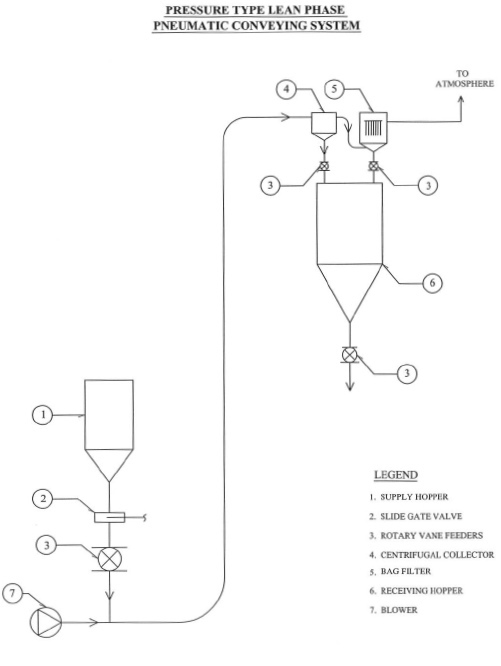
In this type of system, the material to be conveyed is mixed with air under atmospheric conditions i.e., the material is metered into the air stream generally by a rotary vane feeder and thence conveyed to a receiving hopper via centrifugal collector by means of a vacuum pump (mechanical exhauster). At the centrifugal collector, the solids and the air get separated from each other. Air is then exhausted to the atmosphere and material is discharged into the receiving hopper by means of another rotary vane feeder. In addition to the centrifugal collector, a bag filter also may be added to ensure dust concentration in exhaust air is less than 100 PPM or within permissible limits per regulations.

Vacuum type conveying systems are used typically in the applications listed below. Variation of parameters given in (a), (b), (c) is possible and acceptable.
However, combinations shall be such that the maximum vacuum requirement for the system is around 600 mm Hg.
(a) For material with bulk density less than 1,000 Kg/M3
(b) For low conveying rates up to 75 TPH
(c) For short distances up to 100 meters
(d) Maximum vacuum of 600 mm of Hg
Pressure Type Lean Phase System
In this type of system the material to be conveyed is fed into the pipeline through a rotary vane feeder. During the conveying operation the pipeline is under positive pressure. Downstream from the rotary vane feeder the mixing of the material and the compressed air takes place.
The conveying air is supplied by a blower, which transports the material to the receiving hopper via a centrifugal collector. At the centrifugal collector, the solids and the air are separated from each other. Air is exhausted to the atmosphere and material is discharged into the receiving hopper by means of another rotary vane feeder. In addition to the centrifugal collector, a bag filter also may be added to ensure dust concentration in exhaust air is less than 100 PPM or within permissible limits per regulations.
Lean phase type conveying systems are used typically in the applications listed below. Variation of parameters given in (a), (b), (c) is possible and acceptable.
However, combinations shall be such that the maximum pressure requirement for the system is1 Kg/cm2g.
(a) For material with bulk density of less than 1,000 Kg/M3
(b) For low conveying rates up to 100 TPH
(c) For short distances up to 100 meters
(d) Maximum operating pressure of 1 Kg/cm2g
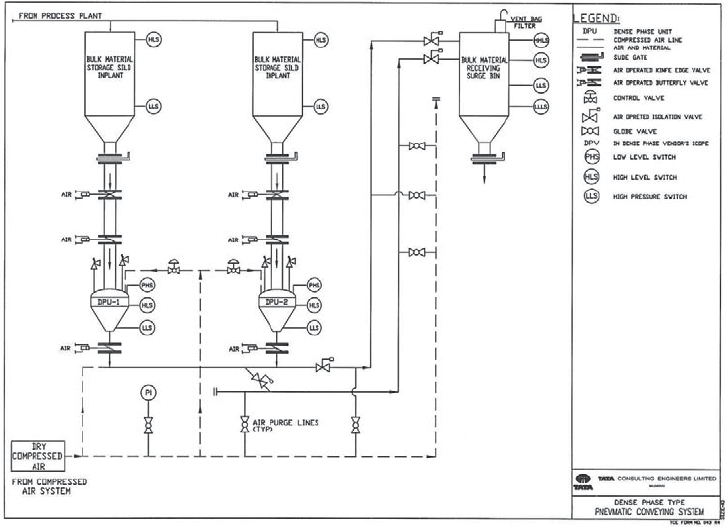
Pressure Type Dense Phase System
In this type of system the material to be conveyed is fed intermittently to a denseveyor (a pressure vessel of cylindrical shape with a conical bottom) from the supply hopper. The filling and discharge of the denseveyor is automatic and is achieved by means of relays or a PLC.
Generally, a PLC-based system is preferred. Material is discharged from the densoveyor in a cyclic manner. Material is conveyed in plug form. Individual plugs of material are conveyed by means of compressed air. Material is discharged into the receiving hopper and air is exhausted generally through a cartridge filter.

Dense phase type conveying systems are used typically in the applications listed below. Variation of parameters given in (a), (b), (c) is possible and acceptable.
However, combinations shall be such that the maximum pressure requirement for the system is 6 Kg/cm2g.
(a) For heavier material with bulk density more than 1,000 Kg/M3 and up to around 2,500 Kg/M3
(b) For high conveying rates up to 300 TPH
(c) For longer distances of 100 metres and more
(d) Maximum operating pressure of 6 Kg/cm2g
IS 8647 “Design Criteria for Pneumatic Conveying Systems” may also be referred to while selecting the type of conveying system to be used.
Compressed Air Systems For Dense Phase Conveying
Compressed air is required to convey the material in the Dense phase system. The conveying pressure is around 6 bar g. The exact pressure depends upon the rate of conveying and distance.
Generally, non-lubricated, two-stage air compressors are employed to generate 6 bar g pressure air. Generally dust free, oil free and dry air is preferred for pneumatic conveying systems. The system consists of air compressors, inter-coolers, after-coolers, air receivers, air dryers, air filters, and plant associated piping, valves and instrumentation.
The compressed air system may be designed exclusively for a pneumatic conveying system. It may also be a compressed air line taken from the compressed air system of the main plant.
Air quality specifications, like pressure dewpoint, are dependant upon the properties of the material to be conveyed and site operating conditions. Properties of material to be reviewed include lump size, bulk density, and the hygroscopic nature of the material. Site conditions play an important role in deciding the quality requirements of compressed air. Factors include minimum and maximum site temperatures and relative humidity (RH) in order to decide which type of air dryers to use and the resulting pressure dew point of conveying air.
Compressed air piping consists of pipes, fittings, bends, valves, flanges etc. Piping material specifications are to be compatible with the material to be conveyed e.g. SS-304 pipes are used for PET chips conveying etc.
Dense Phase Pneumatic Conveying in Power Plants
(1) Coal Handling Systems
The Dense phase system has revolutionized coal conveying in power plants. Coal is fed to the boilers using compressed air. The denseveyor pumps coal through totally enclosed piping ensuring all conveying takes place in a completely dust and spillage-free manner. The system is simple and has no moving parts, drives or bearings. It is suitable for all grades of coal and conveys it as it comes in wet, dry, lumpy or powder forms. There are more than seven thousand successfully working installations throughout the world.
(2) Fly Ash Handling Systems
The need for having an efficient and reliable fly ash handling system is well recognised. This is more significant here as Indian coal may contain as high as 40% of ash in it. The total ash produced from a 500 MW Unit amounts to about 2000 tons per day. Hence a reliable system which can handle such large quantities of ash is required.
There are two principal methods of ash handling, hydraulic and pneumatic.
Coal utilization is associated with the production of two types of ash, namely bottom ash and fly ash. Out of the total ash produced, the amount of bottom ash is about 10-20 % and that of fly ash is 80-90%. Fly ash being a pollution hazard, restrictions are imposed on its disposal. Hence a system is necessary for its collection and disposal.
In India, fly ash is mostly handled using hydraulic methods or pneumatic systems.

In a hydraulic system, ash is conveyed / transported to the disposal area by means of high pressure water. This requires a pump house, pumps, and piping for the system. Ash may be conveyed through open trenches also. This requires large quantities of water. However, with new pollution norms, wherein there are restrictions on wet ash dumping to ash pond, hydraulic systems are not much in use.
A typical thermal power plant generates 500 Mw. The thermal unit can run wholly on coal, although it can take other fuels also. The maximum amount of coal that can be used is 4200 tons per day. With coal of 20% ash content, about 800 tons of ash is generated per day. The Ash handling plant at a thermal power station consists of specially designed bottom ash and fly ash systems.
A typical Dense Phase Conveying System
Fly ash as discharged from various ESP hoppers etc. is collected and conveyed to a silo located in the plant area by means of a vacuum conveying system in dry form. It is then conveyed to another silo located at fly ash aggregate plan area. Denseveyors are used to convey it to the fly ash aggregate plant, with a dense phase type pneumatic system.
The Denseveyor totally eliminates ash fluidization and its high conveying velocity. Fluidization of fly ash at high velocities produces rapid pipe wear and tear and also results in excessive air consumption. The denseveyor pumps small batches of ash in compact slug form at controlled and low velocity. Thus, it ensures both long pipeline life and low air consumption.
System parameters:
Type of Compressors:-Reciprocating, two stage, non- lubricated type.-
Discharge Pressure: 7 Kg/cm2g
Flow rate: - 1200 m3/hr: (FAD)
Conveying rate: 12.5 TPH
Distance – Length of conveying: 500 metres with 14 metres vertical conveying
Type: Dense Phase
Biography
G.D.NIGUDKAR is a graduate from Jiwaji University Gwalior and Post graduate from University of Roorkee-Roorkee. He is Deputy General Manager, TATA Consulting Engineers Ltd.-India. He has 32 years of experience working on handling systems for various thermal power plants, chemical and industrial plants, and nuclear power plants. He has published various articles on conveying systems and compressed air systems in national and international magazines and seminars.
Fore more information please contact G.D.Nigudkar, TATA Consulting Engineers, Mumbai, India.