Single-stage centrifugal blowers are a proven technology that have been around for many years and will probably be here for many years to come. A well maintained machine can last for decades and will likely outlast its original control system. Even if the control system is still in good working order the components might already be end of life and hard to replace if any of them fail. If you are thinking about modernizing the hardware (PLC / HMI / Instruments) this is also a great opportunity to make the system a little smarter and user friendly. Here are a few suggestions to getting the most out of a controls upgrade for your single stage centrifugal blower.
Standby Mode for Easy Testing
A key challenge when upgrading the blower controls at an existing plant is the ability to test the controls without disturbing the process. It feels a lot like doing road construction on a busy highway. Regardless of how thorough the checks are before the first post upgrade run of the machine, there always seems to be some little missing piece of the puzzle that prevents the blower from operating perfectly.
Imagine a wastewater treatment plant with three blowers that is typically running one blower at a time. In order to prevent over pressurizing the header, the running blower must be shut down before the upgraded blower can put air into the process. This is not always convenient since it requires coordination with operators who might be busy with other tasks. A failed start of the upgraded blower can also cause greater upsets to the aeration system by losing process air longer than expected.
A simple improvement that can be made to the control system is the addition of standby mode. Standby mode will allow the blower to begin its normal start sequence but once the main motor is started, it will keep the discharge valve closed, blow off valve open, and vanes at minimum. Therefore, the blower will be running but not putting air into the process. Now that the blower is running, all instruments can be verified to be reading within proper ranges. If any instrument causes the blower to trip and shut down, the aeration system will not be affected. When the blower is running in standby mode this is also a great time to check the EStop. With no back pressure the blower will not surge, thump, and shake the blower building when the Estop is pressed.
Standby mode can be used to not only carefully start a blower but to very cautiously shut it down as well. If the first blower has been fully upgraded and tested, and now it is time to test the second blower, the first blower can be placed in standby mode until the second blower is fully online. Therefore, if the second blower shuts down while transitioning to put air into the process, the first blower can quickly transition back to “process mode” without executing the entire start sequence.
It is important to note that in standby mode the blower should always keep the vanes at minimum. If the vanes are opened with no back pressure from the system, excessive air flow through the blower can potentially stress and damage the impeller.
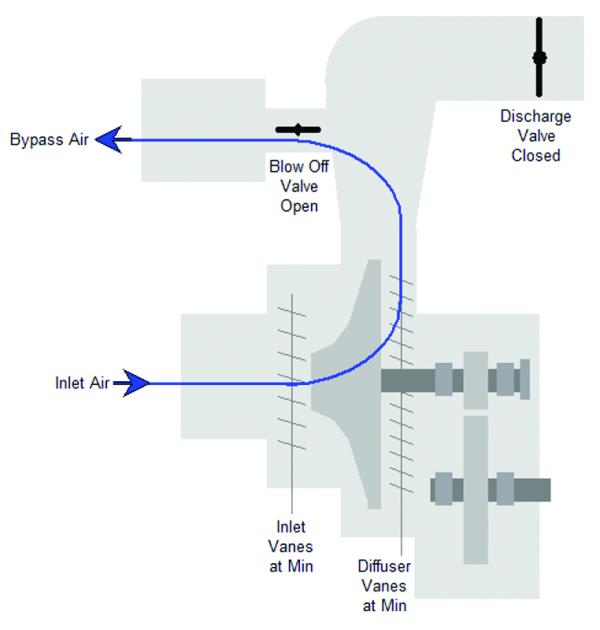
Figure 1 - Blower Running in Standby (No air to process).
Process Variable Capture vs Trending
Trend analysis is an excellent tool for determining root cause failure. However, it is not always convenient when troubleshooting blower issues. Although most blower HMIs have the ability to trend process variables, they were not meant to be historians. Plants that have a DCS or SCADA with a historian are helpful if they have the trend data you are looking for, which is sometimes not the case.
A simple improvement that can be easily implemented on almost any HMI is to capture the process variable’s current value as part of the alarm message. Therefore, instead of an alarm message that reads “High thrust bearing temperature trip” it could also capture the temperature when the blower shut down and read “High thrust bearing temperature trip (220 F)”. One reason to capture this value is to quickly determine if the number is reasonable or not.
Some RTD modules for PLCs can be set to upscale or downscale when it detects a disconnected wire. If the blower shuts down and the alarm message reads “High thrust bearing temperature (1562 F)”, this is obviously from a disconnected RTD wire and not from an overheated thrust bearing. When the on call technician receives the alert, this information will make it obvious that there is a wiring issue, not a mechanical issue with the blower. If the controls are not connected to any type of alerting system, this feature makes it easy for an operator to take a picture with their smartphone and text or email it to the appropriate person.
Process variable (PV) capture can be especially useful for a surge trip. By capturing key process variables a trained engineer or service technician can quickly zero in on the problem. Was the differential pressure 10.8 psi on a blower rated at 9.0 psi when the surge occurred? That would be an obvious reason for the blower to have surged. Instead of thinking there is something wrong with the blower, maybe now is a good time to figure out why all the basin valves pinched down too far and spiked the pressure. PV capture is not meant to replace a SCADA historian but can offer extremely useful troubleshooting information for very little programming effort.
Automated Check Valve Leak Detection
It is possible for a blower to surge during the start sequence if the discharge piping has a failed check valve. If the check valve does not open fully, it can create too much back pressure and therefore surge the blower. A check valve that does not open fully might also not close fully when the blower is off. One option for preventing this type of surge during the start sequence is an adjustable pressure limit. If the differential pressure goes above the set limit during the start sequence, then do not allow the blow off valve to close any further. To determine if the source of the failed start is a faulty check valve, a couple of different methods can be utilized depending on how the blower is equipped.
One way to know if the check valve on the discharge piping has failed is by detecting blower shaft rotation when the blower is off. If the blowers are connected to a common header and at least one blower is running, the header will be pressurized. If the discharge valve is open, or the system does not have a discharge valve, a failed check valve can allow air to leak through and spin the impeller backwards on a machine that is idle. However, not all blowers come equipped with the instruments necessary to detect shaft rotation when the blower is off.
Another option for determining if the check valve is leaking is to perform a simple procedure when the blower in question is off and at least one blower is running. To perform this procedure, note the value of the inlet or discharge temperature transmitters, open the discharge valve, and then close the blow off valve. Wait for a few minutes and see if the inlet or discharge air temperatures rise excessively. If the check valve is not leaking the temperatures will not change. If the check valve has failed, there will be a noticeable rise in temperature. This procedure is a simple but effective method for checking for a leaky check valve. If the hardware is already in place, it takes very little code to add this feature when upgrading the controls.
High Performance Graphics
No upgrade is complete without addressing the graphics. Now is a great time to consider using some of the principles of high performance graphics. There is an excellent book written on this topic titled “The High Performance HMI Handbook” by Bill Hollifield et at, which discusses this topic in great detail. High performance graphics are intuitive and truly make the display a Human/Machine Interface. A simple concept to implement is the use of the indicator / bar graph for showing the setpoint and process variable. For any given setpoint there is an acceptable range. The image below shows an air flow setpoint or 1431 SCFM with an acceptable range of +/- 75 SCFM. Two scenarios are shown where the black triangle represents the PV value and blue band the acceptable range. Using this approach it is quite obvious when the air flow setpoint is being met and when it is out or range.
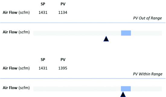
Figure 2 - Tabulated Data vs High Performance Graphics.
Another recommendation from the High Performance HMI Handbook that is worth considering is replacing the old red/green paradigm with dark/light indicators. Imagine being an operator at a plant whose standard color scheme is “red on” and “green off””. Every day on the way home from the plant you must readjust your thinking when you encounter a stop light. Now red means stop and green means go. One advantage of the stop light is that color alone is not the only indicator of state. Stop lights are designed with red at the top and green at the bottom. Therefore, if you can’t distinguish between these colors it is still possible to determine whether to stop or go based on the position of the lights. This is also a principle of high performance graphics which recommends never using color alone as a state change indicator.
Single stage centrifugal blowers have the unique property of limited turn down. I.e., the air flow output at minimum might be 45 percent of the air flow at maximum. Based on this unique property of blowers another possible approach to indicate the on/off state of the blower is with a gauge. When the blower’s main motor is off the gauge reads 0% output, when the main motor is running at minimum (or motor running and in start or stop sequence) 45%, and then scaling the output between 45-100% during normal online operations.
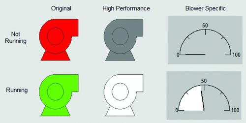
Figure 3 - On / Off Display Methods
Conclusion
These are just a few examples of how the local single-stage centrifugal blower controls can be improved when upgrading the hardware. Software is never done. This is not to suggest that a controls upgrade should be an exercise in endless feature creep. The suggestion is to make it something more than just replacing the hardware. The controls upgrade is the perfect opportunity to incorporate ideas from field service technicians, engineers, and operators, especially operators since they will be using this equipment for the next 20 years.
About the Author
Jeremiah Brown, BSEE, BSCE, has worked as a Controls Engineer for the last 8 years primarily with single stage centrifugal compressors and wastewater treatment aeration systems. He can be contacted at email: [email protected].
To read similar articles on Aeration Blower Technology, please visit
https://blowervacuumbestpractices.com/technology/aeration-blowers.
Visit our Webinar Archives to listen to expert presentations on Aeration Blower Systems at https://www.blowervacuumbestpractices.com/magazine/webinars.