Discussions of aeration blowers tend to be dominated by energy considerations and innovative technology. A stable and normally risk-averse industry has recently begun adopting innovative designs rapidly, largely driven by the growing emphasis on energy and sustainability.
The concerns for innovative technology and reduced energy are well placed. However, the design process isn’t complete when the evaluation has resulted in a blower selection. Most often the blowers are installed in a blower room or blower building. The benefits of optimized blower selection are lost if the installation design isn’t satisfactory. The physical constraints on the installation are largely the same regardless of blower type.
General Arrangement
Many blower projects involve retrofitting new blowers to an existing plant. This can present challenges that don’t exist in greenfield construction. Design compromises may be needed in retrofit projects, but the compromises should not be made at the expense of operator safety or blower functionality.
Footprint – the length and width of each blower skid or package – determines the necessary floor space. In most cases the contractor will make the final equipment selection based on competitive bidding. That requires the designer’s laying out the blower room based on information obtained from several potential suppliers and using the worst-case dimensions.
The most common arrangement is a single row of blowers parallel to each other. This creates a blower room that is longer than it is wide. The inlet and discharge connections are placed closest to the wall and the motors are adjacent to the aisle. This minimizes pipe length.
Occasionally it is advantageous to install the blowers at an angle to the building wall to increase the width of the aisle. Another common arrangement is two rows of blowers with a central aisle between them. [See Figure 1]
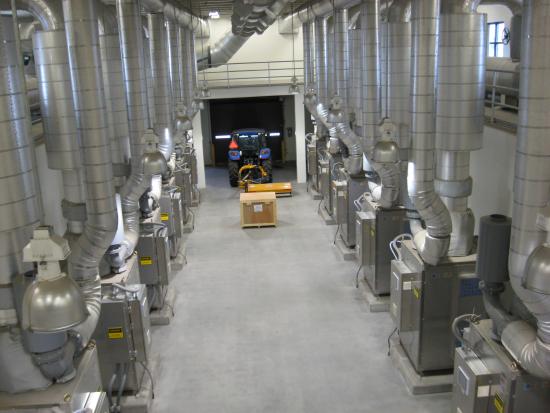
Figure 1: Example Blower Room Layout with Housekeeping Slabs and Generous Spacing for Service Access.
Regardless of arrangement adequate space must be allowed between each blower for easy access for maintenance and repair. This is typically 36” minimum, but more space may be required for large blowers or some packages.
Heat Dissipation
There are multiple sources of heat in any blower system. The most obvious is the heat of compression – the temperature increase that occurs as the air volume is reduced. The temperature increase is a function of the pressure ratio and blower efficiency:
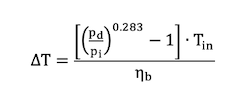
Where:
ΔT = temperature increase, °R or °F
pd,i = discharge and inlet pressure, psia
Tin = inlet temperature, °R = °F+460
ηb = blower efficiency, decimal
Most of the heat of compression is carried away by the discharge air stream. Some heat is transferred from the blower case and piping to the blower room. Piping is often insulated for personnel protection and noise mitigation, making the heat transfer negligible. The blower case may also be insulated or inside a sound enclosure, minimizing room heating.
The rate of heat transfer from bare piping or a bare blower case is a complex phenomenon, involving conduction, convection, and radiation. It is proportional to the area of the warm body and the temperature difference between it and ambient air. The surface of the blower case is usually ribbed or convoluted. For most purposes an estimate of the heat rejected is sufficient:
![]()
Where:
Hb,p = Heat rejected to room from blower or piping, BTU/hr
F = Factor for surface area, F = 1.0 for pipes, F ≈ 1.25 for a ribbed blower case
Td,a = Temperature of discharge air or ambient air, °F
The other major source for heat rejected by the blower system is inefficiency in the electrical components such as motors and variable frequency drives (VFDs). This can be quite substantial:
![]()
Where:
He = Heat rejected to room from electrical components, BTU/hr
Pm = Motor power draw, hp
ηm,VFD = Efficiency of motor and VFD, decimal (ηVFD = 1.0 if constant speed)
Note: 1 hp = 2,544 BTU/hr.
The calculated heat rejected by VFDs is used to size cooling equipment for electrical rooms. If the VFD is in the blower room the large room volume and high rate of heat generation usually makes room air conditioning impractical. It is generally feasible to use forced ventilation with outside air to reduce the blower room temperature to acceptable levels. If the outside air extreme temperature is unacceptably high it may be necessary to provide electrical equipment with enclosures and air conditioning or heat exchange systems to maintain acceptable temperatures.
The ventilation air required to reduce blower room temperature can be estimated:
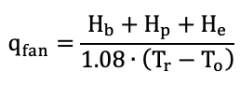
Where:
qfan = Required ventilating air flowrate, cfm
Hb,p,e = Heat rejected by blower, piping, and electrical equipment, BTU/hr
Tr, To = Room and outside air temperature, °F
It is necessary to track where the rejected heat goes. Some package designs keep the heat within the blower enclosure or exhaust it into the blower room. Using heated air for the blower inlet affects performance. Other packages exhaust cooling air and heat outside the blower room, which requires fans and ducting. If water is used in a heat exchanger and is sent to a drain the heat won’t affect blower operation but there will be added costs associated with supplying the water and equipment.
Elevation effects temperature ratings because the reduction in air density reduces its cooling capacity. Most electrical equipment and motors are rated for 3,000 ft above sea level (FASL) or less. Higher elevations may require derating or additional cooling.
Foundations and Cranes
Blowers can represent a significant structural load. Adequate strength is obviously a consideration, but just as important is providing sufficient stiffness to prevent vibration transmission.
Anchor bolts are used for positive displacement, geared single stage, and multistage blowers, but some manufacturers recommend omitting or not tightening the nuts to prevent warping the blower skid. These blowers generally include vibration dampening pads at each anchor point between the skid and the slab.
Packaged blowers generally do not need anchors. They are provided with adjustable levelling feet and are merely set onto the floor slab.
Structural considerations may be particularly vexing in retrofit applications. It is not uncommon to have a basement below the blower room floor to accommodate inlet and discharge piping. This construction was particularly common for large blowers. It is necessary to verify that the slabs and columns are structurally adequate for the replacement blower loads. If the blower room floor is at grade level without a basement the structural considerations are simplified, but adequacy should not be taken for granted.
Housekeeping slabs are commonly used to elevate blower skids above the main floor slab. This simplifies washdown. Reuse of existing housekeeping slabs may dictate equipment layouts in upgrades.
The blower room should have aisles and overhead doors large enough to permit access by fork trucks, flatbed trucks, and lifting equipment. Large facilities and older plants often have overhead cranes installed in the blower room for use in servicing. In new construction it may be more economical to omit the overhead crane and instead make accommodations for portable gantries, mobile cranes, or other temporary lifting devices.
Noise Abatement
All blowers generate noise. The degree to which that creates a problem is a function of several factors:
- Noise level produced – dB(A), a logarithmic scale for representing the noise energy
- Distance – noise energy dissipates inversely with the square of the distance from the source
- Frequency – high frequency noise may be more irritating but is easier to attenuate
- Time of exposure – as exposure time extends the potential for harm to personnel increases
- Room geometry and wall treatment – rooms with reflective walls will be louder
The National Institute for Occupational Safety and Health (NIOSH) has created recommendations for maximum safe exposure time relative to noise level:
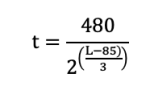
Where:
t = Recommended maximum exposure time, minutes
L = Noise level, dB(A)
|
Recommended Maximum Noise Exposure |
|
|
Noise Level, dB(A) |
Time |
|
80 |
25 hours |
|
85 |
8 hours |
|
90 |
2.5 hours |
|
95 |
48 minutes |
|
100 |
15 minute |
If personnel exposure exceeds these limits hearing protection is necessary. Hearing protection earmuffs can reduce noise levels by 20 to 30 dB(A).
Sound attenuating enclosures are standard for packaged blowers and typically reduce noise to 85 dB(A) or less. Custom noise enclosures are available for all types of blowers, although they may not be cost effective. Other noise reduction methods include insulation on piping, acoustic wrapping blowers, and sound deadening panels or blankets on walls.
For many systems silencers in the inlet, discharge, and blow-off valves are used to minimize noise levels. Silencers may be field installed or included with packaged systems. The blower supplier should be consulted for silencer requirements and construction.
Piping
Blower room piping should be generously sized to minimize friction losses and noise. This entails keeping air velocities in pipe, fittings, and valves low.
|
Typical Distribution Piping Air Velocities |
|
|
Nominal Pipe Diameter |
Design Velocity, feet per minute |
|
1” to 3” |
1,200 to 1,800 |
|
4” to 10” |
1,800 to 3,000 |
|
12” to 24” |
2,700 to 4,000 |
|
30” to 60” |
3,800 to 6,500 |
Silencers, valves, and fittings in the blower room often create more pressure loss than the longer air distribution piping to tanks. The minimum pressure differential needed for opening the required check valves for each blower may be substantial. The specified blower discharge pressure should include these losses.
Flow through a tee branch creates a pressure loss equal to 60 diameters of straight pipe. Whenever possible the connection for individual blowers to the main distribution header should be at 45° to the header to reduce losses. [See Figure 2] This can be particularly helpful when bringing additional blowers online against system pressure.
Inlet air is often drawn from inside the blower room. This necessitates adequate screened or louvered wall openings to accommodate maximum air flow into the room. Whether blower inlet filters are external or part of a package, piped inlets should be considered. In cold climates drawing process air from outside into the blower room can create uncomfortably low interior temperatures.
Discharge headers should be above inlet piping to reduce heat gain by the inlet pipe.
Material selection is not usually critical for piping inside blower rooms. Painted Schedule 40 carbon steel is a common choice, but in larger diameters Schedule 5 or 10 may be more economical.
Blower inlet and discharge flanges are not designed to support the weight of external piping. Full support should be provided for piping. A flexible coupling or expansion joint should be installed between the blower and the piping to prevent transferring loads to the blower case and to accommodate thermal growth.
Flow meters are often installed in blower rooms. Accurate measurement requires uniform velocity across the pipe diameter. Because of limited space and the number of valves and fittings achieving this is problematic. The flow meter supplier should be consulted during design to detect installation issues.
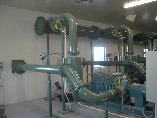
Figure 2: Example Blower Room Layout with 45° Connection to Carbon Steel Discharge Header (Upper Pipe).
Electrical Systems
Blower building layout should include consideration of electrical power distribution equipment. It is common to provide a separate electrical room for motor control centers (MCCs). This is the typical location for branch circuit protection devices, and motor starters for constant speed applications are usually installed in an MCC. If VFDs are used for control they may be in the MCC or part of package systems. If VFDs are free standing it may be advantageous to install them close to the blower to minimize the length of wiring and decrease the potential for electrical harmonics and bearing fluting from induced shaft currents.
Heat dissipation is especially critical for electrical equipment. Most VFDs are limited to 40°C (104°F) ambient temperature, although units rated at 50°C (122°F) are available. It may be necessary to provide cooling systems for VFD enclosures or the entire electrical room. Cooling may be by air conditioners or closed loop water-to-air heat exchangers. Large VFDs offer the option of direct water cooling. Closed loop systems with water-to-air heat exchangers for mounting outside the blower room are available.
Access to enclosures for service is as important for electrical systems as it is for the blower itself. The National Electrical Code (NEC) identifies minimum workspace in front of MCCs and enclosures, but some equipment may need more area. Specific requirements should be verified with suppliers.
Conclusion
Supplying air to process equipment necessitates a system approach. Selecting the blowers is a critical design step, but far from the final one. The layout of the blower room and ancillary equipment is just as critical to project success as the blowers themselves.
About the Author
Tom Jenkins has over forty years’ experience in blowers and blower applications. As an inventor and entrepreneur, he has pioneered many innovations in aeration and blower control. He is an Adjunct Professor at the University of Wisconsin, Madison. Tom is the current Chair of the ASME PTC 13 Committee. For more information, visit www.jentechinc.com.
To read similar articles on Aeration Blower Technology, please visit
https://www.blowervacuumbestpractices.com/technology/aeration-blowers.
Visit our Webinar Archives to listen to expert presentations on Aeration Blower Systems at https://www.blowervacuumbestpractices.com/magazine/webinars.