Most electric utilities offer customer incentives for implementing energy conservation measures (ECMs) Incentive programs pay customers to use less energy. In some cases they are mandated by legislation and in others the incentives are driven by the utility’s desire to avoid building new generating capacity. Some incentives are based on reduced energy use (kWh) and some are based on lower peak demand (kW).
Electricity is a major budget item in municipal and industrial Water Resource Recovery Facilities (WRRFs). Blowers that supply air to treatment processes are the largest single use of electricity in most WRRFs. That makes them a prime target for ECMs. Many blower projects involve replacing or supplementing existing units with new energy-efficient blowers. (Although there is no universal definition, the term “blower” is generally applied to air moving equipment with a discharge pressure between one and 30 psig.)
Measurement & Verification
Most utility incentive programs require measurement and verification (M&V). This allows the utility to verify that the projected energy savings are achieved and the incentive payment is justified. There are two steps to the M&V process. Prior to implementing the ECM baseline energy measurements are taken to establish the existing system’s energy use. When the ECM is implemented the new energy use is measured to confirm the improvement.
There are many metrics used for wastewater treatment energy comparisons. These include kWh per million gallons treated and kWh per pound of Biochemical Oxygen Demand (BOD) removed. In most plants process loads vary seasonally, day to day, and hour to hour. These variations inherently make timely comparison between old and new systems difficult. Blower efficiency is a problematic metric because efficiency is measured in several ways, may reflect the blower alone or the complete blower system, and does not directly identify the energy or power used by the aeration process.
A useful metric for comparisons is specific power. This is usually expressed as kilowatts per hundred scfm (kW/100 scfm).

Where:
e = specific power, kW/scfm.
PE= electric motor power draw, kW.
qstd = airflow rate, scfm (standard ft3/minute at 68°F, 14.7 psia 36% relative humidity).
The specific power is calculated using a single set of inlet conditions and discharge pressure. If the inlet temperature, inlet pressure, or discharge pressure change then the specific power will also change. For accurate comparisons of the performance before and after the ECM, or comparisons of different technologies, inlet and discharge conditions should be consistent. Calculation methods are provided in test codes such as ASME PTC 13 to convert performance at one set of conditions to performance at another set.
The Opportunities
Many existing blower technologies have been in use for decades. These include lobe-type positive displacement blowers, multistage centrifugal blowers, and geared single stage blowers. Other types of blowers, such as the screw blower and the high-speed gearless turbo blower, are more recent introductions to the wastewater treatment field. New control technologies, such as Variable Frequency Drives (VFDs), have provided additional opportunities for ECMs with any blower technology.
These opportunities for energy savings are supported by the utility incentive programs. Many pay up to 50% of the cost of new equipment and installation. Some programs will also help pay for engineering evaluation and design of upgrades.
Measurement of existing blower performance and baseline specific power establishes the potential incentive for a blower replacement. That typically requires field measurement of the critical blower performance parameters: flow, pressure, inlet temperature, and power.
The Challenge
Field measurement of airflow is usually challenging. Accurate flow measurement requires a uniform velocity profile across the diameter of the pipe. The presence of valves and fittings creates distortion in the velocity profile. The compact arrangement of the piping system in most blower rooms decreases accuracy. Flow straighteners may help but are often inadequate in compensating for existing piping arrangements. Few existing blower installations have accurate flow measurement available.
On the other hand, accurate temperature and pressure measurements are straightforward and can be accomplished with simple and inexpensive instruments. A simple pipe tap and fittings are all that is required to insert the instruments into the pipe, and instrument location is not critical. Measuring electric power is also straightforward. If permanent submetering equipment is not available power measurement can be accomplished by qualified personnel with portable instruments and clamp on connections.
Note that regardless of flow measurement method, determination of blower system power is necessary for ECM measurement and verification procedures.
Alternate Methods
There are several alternate methods for determining airflow that can replace direct measurement. These methods may be applicable to only specific blower types or control methods.
Positive Displacement (PD) blowers with known displacement and slip characteristics can use blower speed to estimate inlet volumetric flow. There are some inaccuracies with this method: slip rpm changes with discharge pressure and wear, and the relationship between inlet cubic feet per minute (icfm) and ambient or discharge airflow is affected by pressure drop through filters and silencers. Still, this method provides adequate accuracy for many applications.
Throttled centrifugal blowers often include a “calibrated” ammeter. This uses the correlation between flow and motor amperage to approximate inlet airflow rate. This method is subject to inaccuracy when motor voltage or inlet air temperature changes. This method is not suitable for blowers using variable speed or guide vane control.
Airflow Control Valve Selection – Webinar RecordingDownload the slides and watch the recording of the FREE webcast, presented by Tom Jenkins, P.E., to learn:
|
Another Solution
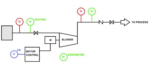
A method based on simple measurements and thermodynamics has been used for many years to accurately determine airflow. Power draw, inlet and discharge temperature, and inlet and discharge pressure are used in conjunction with fundamental thermodynamic equations to determine flow. (See Figure 1.)

Figure 1: Example measurement system.
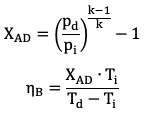
The calculation is performed in two parts. First, the efficiency of the bare blower is determined:

Where:
XAD = Adiabatic factor, dimensionless.
pd = Absolute discharge pressure, psia.
pi = Absolute inlet pressure, psia.
k = ratio of specific heats, Cp/Cv, dimensionless, ≈1.395.
ηB = efficiency of bare blower, decimal.
Td = Absolute discharge temperature, °R = °F + 460.
Ti = Absolute inlet temperature, °R = °F + 460.
The ratio of specific heats, k, is equal to 1.395 for perfect diatomic gases. For air, k varies slightly with temperature and relative humidity. Exact relationships are available in many sources, including ASME PTC 13, but in all but the most extreme cases only minor errors are introduced by using k = 1.395.
Inlet and discharge pressure may be measured directly using absolute pressure transmitters. It is more common to measure gauge pressure on the discharge of the blower. On the inlet side suction measurement identifies the pressure drop through inlet filters and piping. Barometric pressure is used to determine the absolute pressures.

Where:
pbar = site barometric pressure, psia.
pgauge = discharge pressure, psig.
Δpfilter = inlet filter and pressure drop, psig.
Barometric pressure is not a constant. It varies slightly with weather conditions and dramatically with site elevation. The average site barometric pressure can be calculated if the elevation is known.
p_bar=14.7-Elev/2000
Where:
Elev = site elevation, ft above sea level.
Weather conditions will cause some deviations in barometric pressure. The range is less than plus or minus 0.5 psi, even for extreme weather conditions. The variation is commonly less than plus or minus 0.25 psi.
It is possible to obtain the current barometric pressure reading from a weather station or barometer. However, most barometric readings include an adjustment so that the reading is equivalent to sea level readings. This permits direct comparison between different locations. Before using a barometer reading it should be determined if a correction has been used. If so, the appropriate value for site elevation should be applied.
Blower power draw is necessary to calculate the flow rate. Actual shaft power is difficult to measure, so generally the motor power draw is measured and the shaft power calculated from it.
![]()
Where:
PB = blower shaft power, bhp.
ηm = motor efficiency, decimal.
PL = blower mechanical losses, hp
Blower mechanical losses from bearings, gears, lube systems, etc. are typically between one and three percent of motor power.
Three phase power measurement is not always available. In that case the electric power draw may be calculated from measured voltage and current.
![]()
Where:
I = measured motor current draw, Amp, average of three phases.
V = measured motor voltage, Volts, average of three phases.
PF = motor power factor, decimal.
Motor nameplates generally include the full load motor efficiency and power factor. These values vary across the motor’s power range but are nearly constant above 50% power. Values at various power draws are available from motor data tables and should be used if available.
The final step is calculating the blower volumetric airflow.
![]()
Where:
qv,i = volumetric airflow rate, cfm (ft3/minute).
The measured data can be used to calculate the equivalent scfm airflow at standard conditions by ignoring relative humidity.
![]()
This method is similar to the widely accepted thermodynamic pump testing method identified in ISO 5198. Because the temperature rise from compressing air is much larger than the typical temperature rise in pumps the method is actually easier to implement with blowers. Accuracy of the flow value depends on the accuracy of the input data, of course, but the accuracy of this method exceeds flow meter accuracy when installation conditions are marginal.
Some precautions should be taken when the system is used for real time airflow measurement and blower control. During the time immediately following starting of a blower the temperature of the impellers and case have not stabilized. This affects the discharge air temperature and efficiency calculations. The calculated efficiency should be clamped (limited) to reasonable maximum and minimum values. This will prevent gross inaccuracy in the flow calculation. Similarly all measured values should be range checked and the blower should be stopped if signals are lost or outside reasonable ranges.
Accurate Airflow Rates
Utility incentives are based on energy savings. The energy consumption of a blower system is never constant, since flowrate and pressure and temperature are all continuously varying. In order to compare before and after energy consumption, or to compare the consumption of alternate blowers, it is common to use specific power.
Flow meter technology can be very advanced, and if proper installation techniques are used accuracy can be excellent. However, space restrictions often necessitate compromises that negate the inherent meter accuracy. It is often required to obtain measurements on existing installations that do not have flow meters installed. In these situations the thermodynamic testing method can provide accurate airflow rates using simple, inexpensive instruments. The method is suitable to portable devices and temporary instrument installations for ECM measurement and verification as well as real time control applications.
About the Authors
For 25 years, John Conover has worked in the field of compressors and blowers domestically and internationally. He’s an expert in sales, sales management, product and business development, and marketing. John is the Business Development Manager for Air Clean USA.
Tom Jenkins has over forty years’ experience in blowers and blower applications. As an inventor and entrepreneur he has pioneered many innovations in aeration and blower control. He is an Adjunct Professor at the University of Wisconsin, Madison. For more information, visit www.jentechinc.com.
To read similar articles on Aeration Blower Technology, please visit
https://www.blowervacuumbestpractices.com/technology/aeration-blowers.


