When a dense phase pneumatic material conveying system can’t meet the required increase in production without adding an additional system, often the production is increased by just pushing more compressed air into the transfer pipe. But, at some point, the critical particle velocities get so high that the system is now close to a dilute phase. This action is not uncommon and causes many maintenance quality and production issues, and wasted energy.
This article reviews two common pneumatic conveying system types and the importance for each operating plant to know their design and operating parameters particularly conveying air flow velocity and particle velocity profile.
In many manufacturing operations, a significant compressed air use is pneumatic conveying of many types of materials such as cement, fly ash, starch, sugar, salt, sand, plastic pellets, etc. All of these conveying systems use compressed air, or in some cases vacuum, in some form to create pipe line conditions which will allow the product material to flow smoothly in the pipe line to the open end, avoiding production and quality issues.
These conveying systems are usually engineered by the conveyor system manufacture to meet the plants specific production requirements, planned transfer path, and most importantly, their analysis of the specific material. Once installed, tested, and operational, the system should run as designed unless changes are made such as, air flow; pipe line pressure; piping size and/or configuration; and “particle material characteristics”.
Operating Energy Cost
The primary operating energy cost is the source of the compressed air, or vacuum, used to create and maintain the conveying air flow during the transfer time. The higher the required inlet pressure (psig) and inlet air volume (scfm), the higher the inlet compressed air energy cost per scfm/yr.
Figure 1. Relative electrical energy cost to produce 1,000 scfm of compressed air various pressures
|
Based on .05/kWh, 8760 hrs per year, .93 ME |
|||
|
Pressure |
Approximate |
Estimated |
$ scfm/yr |
|
100 psig |
220 hp |
$77,295 |
$154.59 |
|
50 psig |
133 hp |
$46,735 |
$93.47 |
|
15 psig |
92 hp |
$32,355 |
$64.71 |
|
6 psig |
33 hp |
$11,555 |
$23.11 |
Figure 1 shows how pressure ranges dictate the appropriate compressed air source - 50 to 100 psig air compressors or 6 to 15 psig blower air for optimum efficiency (blowers can go as low as <3 psig).
Low Pressure Systems: Dilute Phase Systems under 15 psig
The two most distinct categories of compressed air driven pneumatic conveying are low pressure and high pressure systems.
Low pressure systems, also referred to as dilute phase pneumatic conveying systems, utilize entry air pressure under 15 psig to flow materials through the conveying line at relatively high velocities suspended in the air stream. They are described as low pressure/high velocity systems and have a high air-to-material ratio.
Figure 2. Dilute Phase Pneumatic Material Conveying -- image courtesy of VAC-U-MAX
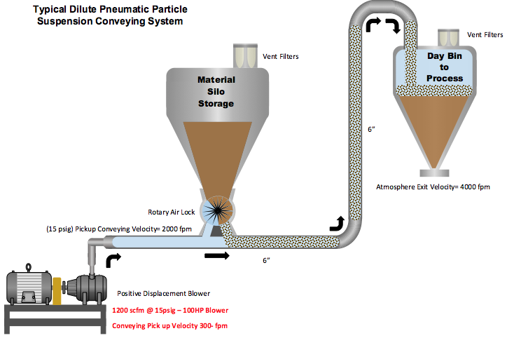
A typical dilute phase, low pressure system will use a pick-up conveying air velocity of around 3,000 feet per minute at the beginning of the system, and about 6,000 feet per minute at the end. The conveying line pressure is 15 psig or lower at the beginning and near atmospheric pressure at the end.
- Particle velocity is very critical. Too low and the product falls from the air stream to the bottom of the pipe. Too high can cause particle-to-particle impact and particle-to-wall impact which will cause product degradation; fouling of the transport pipe walls; and plugging of the pipe. All which exacerbate any wear issues in the pipe and elbows.
- Certain material particles are more susceptible to dilute phase high velocity issues than others. These are:
- Friable Particles - subject to breakage due to impact with each other or the walls can experience product degradation. Too high velocity impact can create heat at the impact points of the pipe line wall and leave coatings of product on the pipe. This can ultimately lead to fouling.
- Abrasive Particles - high velocity may cause significant transport line and elbow wear, creating too high of downtime and maintenance issues (proper evaluation is much more complex than this).
When issues of this type are present, most plants will consider selecting a higher pressure, dense phase pneumatic conveying system.
Dense Phase Systems from 15 to 50 psig
High pressure systems are known as dense phase pneumatic conveying systems. These systems utilize air pressure above 15 psig (up to 50 psig) at the entry and use positive pressure to push materials through the conveying line at relatively low velocities (from 100 fpm to a maximum of 1000 fpm), much like extruding. They are described as high pressure/low velocity systems and have a low air-to-material ratio.
Figure 3. Dense Phase Pneumatic Material Conveying -- image courtesy of VAC-U-MAX
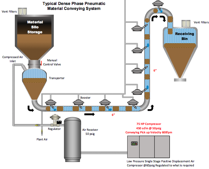
Dense phase conveying uses smaller amounts of higher pressure air to move bulk solid material in slugs through the conveying line. Generally, the product being transported is often abrasive or sensitive to high velocity. The dense phase system is selected to eliminate or minimize transfer pipe wear and other issues associated with higher particle velocity. They maintain the designs moderate velocities and still deliver the appropriate pounds per hour of production. Generally, this type of system requires a compressed air supply of the appropriate size and pressures available (35 to 100 psig). The product and air flow volumes will always be lower than a similar dilute phase system.
Tips when Operating Air Booster/Fluidizer
Many dense phase pneumatic conveying systems use “booster pulsers” also known as “air saver boosters” or “air fluidizers”, to help move the product along the line and free it from the piping or hopper walls. These are usually supplied by higher pressure air (90+ psig). Operating properly, they input short small shots of compressed air, as required, to control the natural solidity of the product pipeline column and maintain appropriate compressed air pipeline velocity. The “air saver boosters” are usually carefully set and controlled to optimize the expensive high pressure air and not destroy the product column’s solid integrity. Key tips to keep in mind when operating air fluidizers in the pneumatic conveying systems:
- More air will not improve performance. Measure, identify, and control the minimum volume of air to do the job correctly.
- Run the air only when the vessel is discharging. Running the fluidizers when the discharge is closed may create voids in the material, interfering with smooth flow.
- Run multiple fluidizers sequentially, not simultaneously. Use shortest pulse time with longest interval possible.
- Take the time to design the best possible timing of the pulsers with measured data in conveying air and particle velocity. Establish optimum timed pulse aeration for each product and adjust accordingly.
Case Study: When Dense Phase Becomes Dilute Phase
The following case study is a dense phase material transport system unable to meet the required production demands. Background: The pneumatic transport system fills five supply silos with the appropriate material to be mixed and sent on to production. There are two 6” production lines to the processes.
At the current production levels, the batch transporter system needs to constantly handle 30,000 pounds per hour of mixture. In order to establish a 2-hour cushion of supply in the day bins, the system must be capable of runs of 90,000 pounds per hour. In order to reach these required transport levels, the basic system was adjusted by raising the pressure and extending the cycles of the air boosters. The boosters are currently all running full open constantly with feed pressures from 30 psig to 90 psig as adjusted.
Today, the measured average flow through the 6” transport system is 1,500 scfm average (velocity up to 3,825 ft/min), and sustained peaks of 2,600 scfm (velocity 6,640 ft/min). The outcome? This plant unknowingly converted their dense phase system to dilute phase. These air velocities and probable particle velocities are high even for a dilute phase system. The calculated conveying air velocity is based on the entry pressure, but with all the booster feeds and higher volume of air the estimate of pipeline pressure to calculate particle velocity is rough at best.
Results After Plant Modifications
Figure 4. Increase on Conveying Air / Particle Velocity
|
Production Rate |
Increased |
Does Meet Production When Running |
|
Original Energy Cost |
1000 fpm (392 scfm @ 50 psig) |
392 x $64.71 scfm/yr = |
|
Current Energy Cost |
2000 scfm average – 392= additional 1608 scfm @ 100 psig produced |
= 1608 x $154.39 = $248,259/yr |
|
Total Current Energy Cost |
$248,259 + $25,366 |
8760 hrs/yr = $273,625/yr |
|
Values are based on 8760 hrs/yr |
The plant runs the system at about 45% utilization |
|
|
Estimated Original Energy Cost |
$11,414/yr at 45% utilization |
|
|
Current Energy Cost |
$123,131/yr at 45% utilization |
|
|
Net Increase in Energy Cost |
$111,716/yr at 45% utilization |
|
Product quality has faced issues. The scrap rate of the product conveyed increased about 20% over the last three years, according to plant personnel. No specific value was available. Pipeline repair, maintenance and downtime have gone from a non-issue to a constant problem. no specific value was available.
Future Short Term Action Plan: Measure the “actual particle velocities” of each product at critical locations with a non-invasive, particle velocity monitor and control system to set up an accurate particle velocity profile. Simultaneously at strategic locations, measure the actual pipe line pressure and using the measured inlet flow, calculate the conveying air velocity. This will provide an accurate conveying air velocity/particle velocity profile.
Identify the operating profile of the particle speed to find the safe zones and try to maintain these levels. Keep production levels up along with minimizing quality and maintenance issues.
Future Long Term Action Plan: With proper data, plant personnel can evaluate the economics to convert to an improved dilute phase system - or add additional dense phase systems as required to reach the production levels.
At this point, the plant has the worst part of both types – high energy cost of compressed air for dense phase, but high volume of dilute (scfm) phase at the same expensive air, and high particle velocities driven issues of dilute phase. The measurement data acquisition plan will not only help to get to the optimum system, but will be a key in maintaining optimum performance on a long term basis.
For more information contact Hank van Ormer: [email protected].
To read similar articles on Pneumatic Conveying Technology visit /technology/conveying.