By Tie Duan, E.W. Klein & Co.
02/17/2021
Deciding on the most suitable vacuum technology for an industrial application can be challenging. This decision can be relatively easy if it is simply finding a drop-in replacement for an existing pump, but if a process keeps crashing an existing pump, it can get complicated when you are tasked with re-evaluating all the available options to find the best solution. I am hoping to highlight a few key factors to consider when you run into this type of scenario. Some of these key considerations are:
- Operating vacuum depth
- Volumetric flow rate
- Process gas, liquid, and solids
The first two items can be somewhat straight forward, but the last criteria can introduce a lot of nuances into this decision. Below is a more detailed breakdown of each of these criteria.
Operating Vacuum Depth
Below is a reference chart we frequently use to help guide our customers in choosing the right vacuum technology-based on their process’ operating vacuum depth.
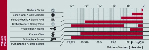
Vacuum Depth Chart. Image used with permission from Gardner Denver.
Different vacuum technologies have different ranges of achievable vacuum depths. This is due to the operating principle of each technology. Below is a high-level overview of these technologies’ vacuum depth capabilities:
- Side channel blower (regenerative blower). These blowers are mainly designed to produce large airflow with relatively small footprint, but at the sacrifice of vacuum depth. Their designed max vacuum depth (ultimate vacuum) typically does not exceed 10 in-HgV. A look at their internal design reveals the cause behind this limitation.
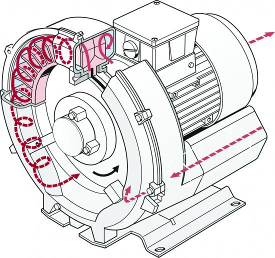
Cutaway View of a Side Channel Blower. Image used with permission from Gardner Denver.
There is significant space between impeller blades and the inner surface of the housing. This space allows the inlet air to be transported between each impeller cavity which creates the vacuum, but it also acts a large air leak within the pump itself, results in slippage, preventing it from reaching deeper vacuum.
- Liquid ring vacuum pump (LRVP). Because a LRVP often uses water as the liquid to seal the clearance between the rotor blades and the housing, it minimizes air leak within the pump itself, therefore allows a single-stage LRVP to reach down to 29 in-Hg. For Nash’s two stage TC pumps, they can reach even deeper than 29 in-Hg. However, the ultimate depth of a LRVP is often limited by the seal liquid used, more specifically by its vapor pressure. As vacuum deepens, the boiling temperature of the seal liquid drops, at the same time pump motor, heat from compression, and the process all add heat to the seal liquid. The ultimate vacuum of a LRVP is reached when the boiling temperature of the liquid under vacuum equals the temperature of the seal liquid, then the pump will most likely cavitate and not go any deeper in vacuum. Alternatively, oil and other liquid with different vapor pressures can be used as the seal liquid in a LRVP to achieve deeper vacuum.
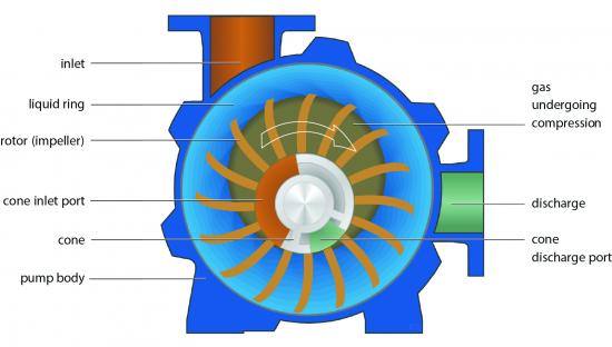
Cross Section View of A Liquid Ring Vacuum Pump. Image used with permission from Gardner Denver.
- Rotary vane vacuum pump (oil-lubricated). As its name suggests, an oil-lubricated rotary vane pump uses oil to seal any gap between the vanes and the inner surface of the housing, therefore allowing a deep vacuum. Because oil is essentially used as the seal liquid, it can achieve deeper vacuum than typical LRVP using water as seal liquid.
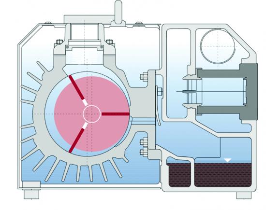
Oil-Lubricated Rotary Vane Pump. Image used with permission from Gardner Denver.
An oil-less rotary vane, however, can only reach about 25 to 26 in-HgV, because there is no seal liquid to prevent air leak between the vanes and inner surface of the rotor housing.
- Claw pump. Like an oil-less rotary vane pump, a claw pump can reach 26 or 27 in-HgV, but not any deeper in continuous operation. The space between the two rotary claws and the inner surface of the housing allows small amount of air leak within the pump. The heat generated from the compression cycle of the claws’ rotation also limits its ultimate vacuum depth. The deeper the vacuum, the less airflow and less heat removal by inlet air, resulting in claws’ thermal expansion and eventual touch off.
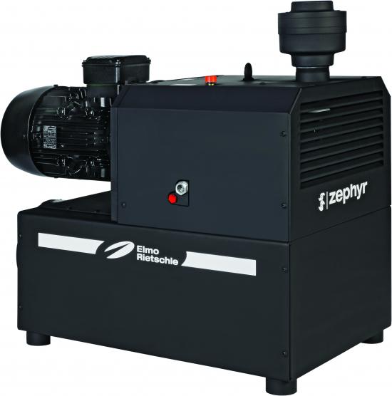
Claw Vacuum Pump. Image used with permission from Gardner Denver.
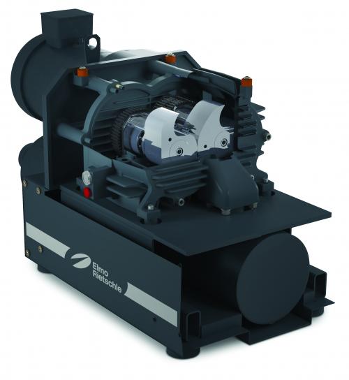
Cutaway view of Claw Vacuum Pump. Image used with permission from Gardner Denver.
- Screw pump. The dry pump has a much deeper ultimate vacuum than an oil-less rotary vane, claw pump, or LRVP. This is due to the two synchronized counter-rotating screws continuously compress and cool the inlet gas along the entire axial direction. A screw pump can reach deep into 0.02 Torr (0.03 mbara) and can run completely deadheaded.
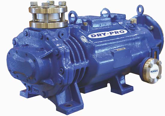
VSB Screw Vacuum. Image used with permission from Gardner Denver.
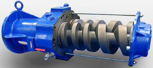
VSB Screw Pump Internal View. Image used with permission from Gardner Denver.
- Roots blower. The chart shows two effective vacuum ranges for this type of blowers, one at rough vacuum like that of a side channel blower, and one at deep vacuum close to that of a screw pump. This blower is frequently used as an alternative to side channel blower for vacuum material conveying applications that requires large air flow and relatively low vacuum depth. The roots type blower is also used as a booster pump in combination with an oil-lubricated rotary vane, LRVP, or screw pump to achieve very deep vacuum with high CFM capacity.
Volumetric Flow Rate
When calculating the volumetric flow rate needed by a vacuum pump, it is important to distinguish between SCFM (Standard CFM. Standard is defined as under standard pressure and temperature conditions. The accepted standard of temperature and pressure are 68 °F(20°C) and 36 percent humidity at sea level) and ACFM (Actual CFM). SCFM is typically the volumetric flow rate the process requires; ACFM is the volumetric flow the vacuum pump sees at operating vacuum depth. Because of the volumetric expansion of air under vacuum, ACFM will be equal to or greater than SCFM. The deeper the operating vacuum the larger ACFM is compared to SCFM. Below is an Expanded Air Ratio chart in relation to vacuum depth measured in in-Hg gauge.
How to Correctly Size Vacuum Pumps – Webinar RecordingDownload the slides and watch the recording of the FREE webcast to learn:
|
For example, a side channel blower application that requires only 10 in-HgV vacuum, 100 CFM process needs a blower with at least 150 ACFM capacity. For a liquid ring vacuum pump running at 27 in-HgV vacuum, a 100 CFM process needs a pump with at least 1000 ACFM capacity.
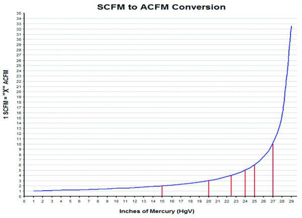
Expanded Air Ratio Chart
Process Gas, Liquid, and Solids
While no vacuum pump is a trash can, different vacuum technologies have different levels of tolerance to accidental ingestion of process gas, liquid, and solids. If we are to put them on a scale from Crash and Burn to Keeps on Truckin’, they can be arranged like below:

Managing process carry-over requires a suitable strategy of inlet separation, filtration, and condensation. This is heavily process dependent and involves a lot of nuances. A simplified motto for dealing with process carry-over is to knock it out or pass it through. Either we prevent process carry-over from reaching the pump or allow the carry-over to pass through the pump without causing damage to the equipment or process. For this article, I will list a few scenarios that highlight each vacuum technology’s interaction with potential process carry-overs.
- Use solvent or compatible chemical as seal liquid in LRVP. One recent application we worked on had the potential of introducing chemicals that can condense in the LRVP’s water loop and clogging up the seal liquid line. One solution option was to substitute water with a solvent as the pump’s seal liquid, which can prevent this chemical from clumping inside the pump. Another application had the concern of alcohol vapor from the process being pulled into the pump mixing with seal water, requiring secondary separation and recovery. A solution option was to seal the pump with alcohol, so discharged fluid is ready for recovery without further separation.
- Polymerization in the claw pump. Because of the claw pump’s operating principle, it generates significant heat during its compression stage. This heat when met with certain monomers pulled into the pump can result in polymerization on the claws and lock up the pump. A more common solution for this is to knock out the incoming monomer using a condenser and separator.
- Oil-water emulsion in a rotary vane. In an oil-lubricated rotary vane pump, when water vapor is sucked into the pump, water can mix with oil and create an emulsion that can damage the internals of the pump. A couple of solutions: use gas ballast to eject water vapor in the compression zone; dead head the pump to boil off the water under deep vacuum periodically.
- Screw pump’s temperature too low. For a screw pump, it is often used to pass through process gas or vapor without condensing it in the pump. Therefore, a screw pump needs to run at a controlled elevated temperature to prevent condensation of harmful vapors. We have seen customers where either the cooling water is too cold or the VFD is running the screw pump at too low of RPM, resulting in vapor condensing in the pump causing it to lock up or corrode. Furthermore, starting and shutting down a screw pump also requires a period of warm up and purge. These pre-programmed procedures are meant to ensure the pump reaches optimal temperature before it is exposed to condensable vapor, as well as remove any vapor left-over before the pump cools down in shutdown.
- Clogged filter crashing side channel blowers. A side channel blower generates a lot of heat as well, because of its constant compression of inlet air. It also uses the process air to cool itself down. It is not uncommon to see a side channel blower being used in a dusty application getting its inlet filter clogged, preventing fresh air from entering the blower to cool it down. The blower’s impeller would eventually grow under heat and touch off the housing and crash.
Every process and application is a little bit unique, so a unique solution or solution variation is needed.
E.W. Klein & Co. Celebrates 100 Year AnniversaryOnly a handful of companies last 100 years, and E.W. Klein is beginning the celebration of its 100th anniversary thanks to you and the great companies we represent, such as Gardner Denver, Alfa-Laval heat exchangers and other equipment. Founded in 1921, E.W. Klein & Co. is a leading manufacturer’s representative of engineered vacuum and heat transfer equipment to the chemical, paper, power, and general industrial markets. Our Roots: Based in Atlanta, E.W. Klein was selected as Nash Engineering Co’s first representative in 1921. Nash’s original focus was on steam heating systems common in buildings of that time. Later, Nash developed their world-famous line of Nash Hytor vacuum pumps. Still a leader in vacuum today, Nash is now part of the Gardner Denver product line recently merged with Ingersoll-Rand.
2020 was a challenging year for us all. Since the founding of the company back in 1921, E.W. Klein & Co has come through all kinds of difficulties: wars, depression, recessions, natural disasters, stock market crashes, a pandemic, and everything in between. Through it all, it has been the people of E.W. Klein – our employees, great customers, and the equipment we represent – who have made the difference. COVID has taught us that we can make it through the tough times and make sure we celebrate the good ones too, now and for the next 100 years. Looking forward to 2021 and past COVID: A part of our overall growth plan was moving to a new location that has allowed us to stock and repair pumps and other equipment that we represent. We are excited about our new capabilities that will allow us to service the customer better than ever. The keys to our success have always been our dedicated technical-focused staff, developing strong relationships with our diverse customer base, and capitalizing on new opportunities. For more information about E.W. Klein and the great companies we represent, please visit www.ewklein.com.
|
About the Author
Tie Duan is the Solutions Sales Engineer at E.W. Klein & Co. Email: tie@ewklein.com, tel: 478-508-2017
For similar articles on Industrial Vacuum Technology, visit https://www.blowervacuumbestpractices.com/technology/rough-vac.
