We often get asked, “Do I need a receiver tank with my vacuum system?” or “Would my vacuum system’s issues go away if I just had a bigger vacuum system?”. This often leads to a great educational discussion with the customer about vacuum storage and dispelling some of the myths surrounding it that are regularly spread around without realization. Vacuum receivers are often misunderstood as they are likened to similar systems like compressed air or other compressed gases, where a host of benefits can be gained by adding storage to the system in the form of a well thought out receiver tank or storage vessel.
Receivers Tanks – What Do They Do and Why?
Storage vessels are everywhere in fluid and gas systems whether it’s for managing an excess of product, storing gas or liquid for sudden surges in demand, providing a means to separate liquids from gas steams, or a somewhat stable location to monitor and measure pressure or temperature. They’re so plentiful in their uses that they sometimes get used where they’re incorrectly sized, cause restrictions in flow, or just aren’t needed at all.
In this article, we’ll discuss some of the uses for receiver tanks for positive pressure systems where the pressure inside the system is greater than atmospheric pressure, and the uses, or lack thereof of, receiver tanks in vacuum systems where the system pressure is less than atmospheric pressure.
Positive pressure systems, like a compressed air system, benefit a vast majority of the time from carefully placed receiver tanks. Typically, we’d recommend the use of a receiver tank on a compressed air system to act, at a minimum, as a good control point where the air is forced to slow down inside the receiver.
How Is Flow Affected by Changes In Pipe Area?
Flow is derived from the below equation where Q is the flow of your fluid/gas in terms of volume per time (i.e., cubic feet per minute, gallons per minute, cubic meters per hour, etc.), v is the velocity of the gas or the speed at which the gas is moving, and A is the cross-sectional area of the pipe the gas is traveling through:
Q=v
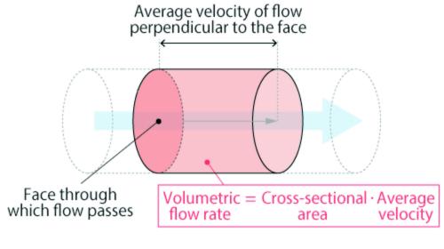
Figure 1. Volumetric flow rate through a pipe is directly proportional to the cross-sectional area of the pipe.
Assuming there is not flow lost going into a receiver (no leaks) then the flow in the pipe (call it Q1) is the same as the receiver (call it Q2):
From that we can say:
And go one step further:
v_1
However, the cross-sectional area of the pipe is not going to be the same as the receiver. The cross-section area in the receiver is typically much larger than the piping. To keep this equation in balance, if the cross-section area A2 > A1 of the piping, then the velocities will have the opposite relationship where the velocity in the pipe (v1) will be proportionally greater than the velocity in the receiver which can be shown as the below:
v1 * A1 = v2 * A2
Which we can show as:
v1 A2
_____ = ___
v2 A1
To summarize - the larger the cross-sectional area of the receiver, the slower the gas will move through the receiver. If there are any liquids or solids suspended in the gas stream due to the high velocity before the receiver, they will start to fall out of the gas stream once the gas slows down inside the receiver. Commonly in compressed air systems this is seen in the wet-side receiver tank (after the compressor and before the dryer) where a significant amount of water accumulates inside the receiver and must be regularly drained or it can spill over into the other parts of the process.
How To Separate Out Liquids From the Air Stream
Changing the direction of the flow also helps slow it down even further. For example, if the gas enters into the receiver tank at the bottom and discharges out the top of the receiver, not only do we get the benefit of the reduced velocity from the increase in cross-sectional area, now we also get gravity working in our favor.
Suspended liquids and solids in the gas stream need additional energy to be lifted against gravity to the discharge, and if there is not sufficient “oomph” to get them through, then they’ll fall out of the stream and collect at the bottom of the receiver, ready to be drained away or collected.
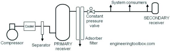
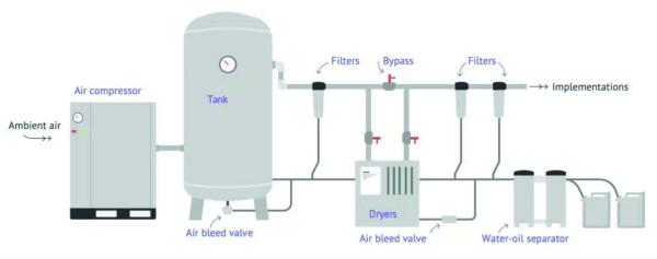
Figure 2. Note that the compressed air receiver is drawn with the inlet side on the bottom from the compressor and discharges out the top.
Pressure Drop Through Piping
There’s an important facet to discuss related to change of direction of a gas stream, which is pressure drop. Gas doesn’t flow neatly through a pipe like an orderly highway where all cars are staying in their lanes and not hitting one another. It’s a chaotic madhouse with the gas swirling everywhere, and with each twist and turn, the gas molecules speed up and slow down colliding with the piping and one another as they make their way through the piping bends, elbows, T-fittings, going in and out of receivers, filters, etc.
This is true of compressed gas and vacuum systems. Each collision reduces the energy of the flowing gas meaning more “oomph” is needed to push or pull the gas through the pipe. This commonly shows itself as pressure drop through piping.
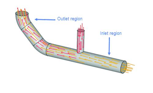
Figure 3. Pipe flow showing a T fitting inlet to a main header. Fitting arrangements like this can add higher pressure drop, especially with vacuum systems. Flow should join in the direction of flow instead of perpendicular in order to reduce system pressure drop.
Receivers aren’t normally thought of as areas of pressure drop, but they can be if they’re not appropriately sized or plumbed to the system. For example, if you were to plumb your receiver tank into a vacuum system where you’re creating a tortuous path for the gas to drop out some liquid, that same tortuous path might also be causing a notable pressure to drop in the vacuum system which could lead to other issues like not meeting the required vacuum at your end of line.
If there’s not going to be liquid in the gas stream, then maybe the receiver tank should be plumbed to provide as straight through of a flow path as possible for the gas stream to reduce pressure loss. The benefit of storage from the receiver tank will still be there, but the pressure loss will not be – seems like a win-win. But how much storage does one really get from a vacuum receiver?
How Does A Receiver Tank Work With Vacuum?
Using a receiver tank with a positive pressure system is pretty self-explanatory – it provides an extra space where a compressor can shove extra gas into, increasing the pressure in the receiver, and keep that extra gas for a later time. The receiver tank is effectively holding on to extra gas molecules (and the more there are, the higher the pressure will be in the receiver) to be used later.
Now let’s think about this in terms of vacuum. Vacuum is when there’s less pressure, or less gas, in a space than there is outside of that space in the atmosphere. So, if we are to use the same example of storing vacuum as we did store pressure, we would have a receiver tank where we want there to be less gas molecules than the rest of the system.
That receiver tank isn’t storing anything really – in fact the only thing there is more of in that receiver would be empty space. And empty space is nothing. So, the only thing you’d be storing is – you guessed it – nothing.
Well maybe not exactly nothing since vacuum is all about the differential pressure needed between what is in the system and the atmosphere surrounding it and trying to get that “more of nothing” you’ve stored to work for you. In a positive pressure system, a receiver’s ability to store a higher pressure than is needed and provide a source of gas for large, sudden needs OR for times when the compressor is off or unloaded, and a small amount of gas is needed, then having it come from the receiver tank instead of needing to turn on the compressor, is a huge benefit.
How Much Storage Does A Receiver Tank Really Provide?
https://www.metron.energy/blog/compressed-air-industry-energy-optimization/
Let’s say you have an imaginary company that makes great widgets, and you have a process that needs air at 100 PSIG. You have a compressor connected to a 100-gallon receiver tank and a regulator. The compressor is controlled by a pressure switch. That means it will turn on and run until the pressure is at the upper limit and will turn off until the pressure in the receiver tank is at the lower limit (i.e., 100 PSIG). That way you will always have air at 100 PSIG ready to use. Seems easy enough. Let’s complicate it.
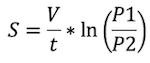
Say your compressor makes 10 CFM at all times regardless of the discharge pressure and the receiver tank can withstand up to 10,000 PSIG (which isn’t 100% realistic but we’re talking about an imaginary company that makes widgets so let’s not get carried away). Your process needs 20 CFM but only for one minute every 20 minutes and you can’t run your compressor during that time because the power gets turned off to the compressor (I don’t make the rules, just this imaginary scenario). How is this going to work? Don’t forget your receiver. Just up your pressure switch control to a higher pressure. How will you know how high to turn it – just use the below equation for pump down of a vessel:
S=V / t
S = Average flow in cu. ft / min.
V = volume in cubic feet
t = time in minutes
P1 = starting pressure (high pressure) PSIA
P2 = end pressure (needed pressure) PSIA
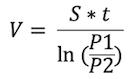
We want to solve for P1 to know how high we need to run up the pressure in the receiver, so we’ll have enough to use only the air in the receiver. That turns the to the below:
![]()
And in our case:
S = 20 cu. ft / min.
V = 100 gal OR 13.3681 cu. ft.
t = 1 minute
P2 = 100 PSIG = 114.7 PSIA
Plugging all that into your handy calculator you will get this:
![]()
P1 = 512 PSIA = ~497 PSIG
So, you’ll need to adjust your compressor to run up to 500 PSIG in order to have enough air to supply that 20 CFM load for one minute without running your compressor. Neat!
Same example but we need air for more than one minute – say 5 minutes – where does that put us?
![]()
P1 = 203376 PSIA = A LOT
Wow – 200,000 PSI to run your system for just 5 minutes of air. Now where will you find a real compressor that can do just that? I’ll save you the trouble of looking – nowhere. So how do we get around that? If that high of pressure is out of reach, then let’s make our receiver bigger instead. Instead of 100 gallons, let’s use 1,000 gallons.
Same equation, just increase the volume by a factor of 10 to 133.681 cu. ft. to get:
![]()
P1 = 242 PSIA
Now that’s way more achievable and quickly leads us to the conclusion that more storage can allow for a lower pressure operating band than a system with less storage. But how does this work for vacuum systems?
How Much Storage Does My Vacuum Receiver Provide?
Let’s use a similar example but with a vacuum system. Your same company has a vacuum pump and a 100-gallon receiver. The pump can move 10 CFM of air to pull vacuum on your receiver tank. If we have a similar scenario where you need 20 CFM of vacuum for one minute with your 100-gallon receiver, and you need 20 in HgV, how much pressure differential is needed?
Using the same formula as above but keeping in mind that our pressures are inverted (P1 is our high-pressure number or ending vacuum, P2 is our lower pressure, or our beginning vacuum, which we want to solve for):
![]()
And fill in with our new information:
S = 20 cu. ft / min.
V = 100 gal OR 13.3681 cu. ft.
t = 1 minute
P1 = 20 inHgV PSIG = 9.92 inHgA
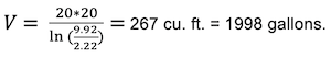
Then solve for the needed initial pressure:
![]()
P2 = 2.22 inHgA = 27.7 inHgV
So, what does this tell us about our vacuum receiver? If we draw down our 100-gallon receiver an additional 7.7 in HgV then we get our flow. 7.7 in HgV is only 3.78 PSI. Doesn’t seem like a big difference, does it? In fact, with vacuum, we only have 14.7 PSI of total differential that we could ever get. Which brings us to question, is doing all this work to draw down the vacuum receiver worth the small margin it brings us?
Now same as above – storage for 5 minutes is what starting pressure?
![]()
P2 = 0.005594 inHgA = 29.91 inHgV
That means we’d need to draw down the receiver ~9.91 in HgV or about 4.87 PSI. Seems easy enough. But now we’re running into a potential issue – how deep in vacuum can we go?
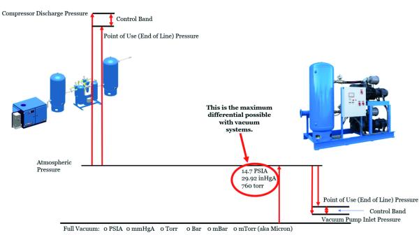
The maximum vacuum possible (absolutely no pressure) is 29.92 inHgV. So, with our last example requiring us to use 99.996% of all the differential available, we start running into some other physical barriers.
Basically, we are running out of pressure to use. There’s a finite amount of gas when starting at atmosphere and pulling down into vacuum. The deeper we go in vacuum we are looking at chasing individual molecules to get the needed vacuum in order to provide the flow needed from the receiver. That is a task much easier said than done. Compressing gas is basically packing more and more molecules of gas into a finite space. Chasing down, catching, and removing single molecules of gas in a finite space is a tedious hunt and there’s incredibly specialized vacuum pumps that do just that, but they’re out of the price range for many people.
So, let’s increase our receiver size to try and get back to where we only need to draw down an additional 7.7 inHgV since that falls within the reasonable range for most vacuum pumps out there.
Going back to our first equation for pump down, instead of solving for pressure, we’ll solve for Volume (V):
Solving for V:
Now plug in what we know:
S = 20 cu. ft / min.
t = 20 minute
P2 = 2.22 inHgA
P1 = 9.92 inHgA
Solve for how much volume we would need:
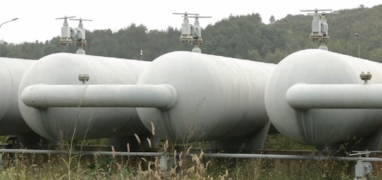
Woof. That’s a pretty big receiver tank that you’d need, and this is a relatively small flow required as well. If we think in terms of a large industrial operation where maybe they need 2000 CFM and want storage for even just 2 minutes (just long enough for their backup system to come back online in the event of a failure) then that system would require 2671 cu. ft. or 19,987 gallons of storage. That’s a ton of real estate needed to store essentially an empty receiver tank or set of tanks for such a small gain of differential pressure.
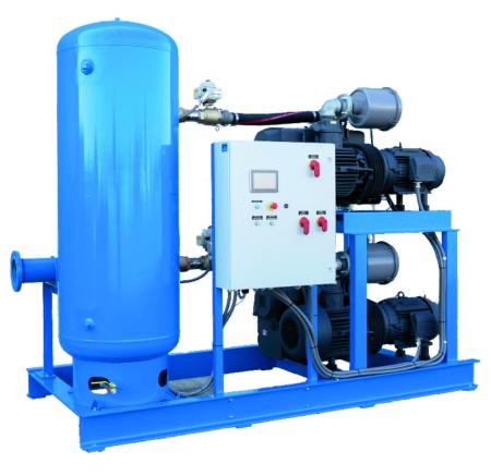
Something similar to the below would be needed in order to provide that much storage – and that’s just not realistic in most cases.
If adding a 20,000-gallon receiver tank isn’t an option, how else can one add storage to their vacuum system? One easy way is the system piping. In this same case where we have a 2,000 CFM vacuum system, that would typically require about 8-inch piping. If that same system has approximately 500 feet of piping, the total volume of that pipe ends up being ~1300 gallons. And that’s not considering all the small drops off that main header, all of which will add to the total system volume.
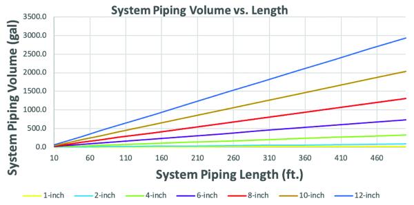
So, what does this tell us? Piping in vacuum systems, which is normally designed to be larger in diameter to reduce pressure drop in the system, will provide more storage than a receiver could. So simply increasing the size of the system piping will yield a significant increase in storage, decrease pressure loss, and have the additional benefit of providing some room for additional capacity. It also doesn’t require a large tank to eat up valuable real estate that could be used for some other equipment that could be more profitable for the customer. This is typically our recommendation for vacuum storage due to the multiple benefits larger diameter piping will provide.
Are Vacuum Receivers Needed?
While vacuum receivers might not work as well as a positive pressure receiver in terms of providing additional capacity to deal with surges in demand or storage, they are still useful devices if used appropriately and for the right reasons. Using a receiver tank to act as a separator to remove liquids from the gas stream can be a critical use of a receiver tank to protect the respective vacuum pump system from ingesting the liquid, which can crash some types of vacuum pumps.
Liquids can also be removed from gas streams using liquid filters through centrifugal action, change of direction, and screens or meshes to collect and remove liquids – many of which have a smaller footprint than a larger receiver tank. So, if liquid removal is your goal – there may be multiple solutions available. There are specific systems designed to separate out and drain liquids under vacuum without needing to bring the whole system to a halt and vent it to atmosphere since liquids under vacuum won’t drain out to atmosphere all on their own.
An inadequately sized or misplaced receiver tank can also cause significant pressure loss. If it’s been sized appropriately then the pressure drop should be negligible, however, if the porting is too small it could present as a restriction especially during a system pull down (i.e., pulling the vacuum system down from atmospheric pressure) or during high flow situations. Porting on the receiver tank should be no smaller than the inlet ports on the respective vacuum pump(s), and if there are multiple pumps then the ports should be sized for the maximum flow possible through the system.
It’s always crucial to consider how your vacuum system operates – whether it’s a relatively constant demand or cyclically pulls down and then vents to a lesser vacuum, when picking any component to use, whether it’s the vacuum pump, system controls, variable speed drives, filters, or receiver tanks. Each component can be a great benefit if used appropriately.
For more information or any questions, call the Rogers Machinery Company at (503)-639-0808 or visit the Engineered Systems Solutions page at www.rogers-machinery.com.
For similar articles on Industrial Vacuum, visit https://www.blowervacuumbestpractices.com/technology/rough-vac.
Visit our Webinar Archives to listen to expert presentations on Industrial Vacuum Technology at https://www.blowervacuumbestpractices.com/magazine/webinars.
March 2024