In the first of this two-part series on the basics of aeration control valves we examined valve fundamentals and basic equations for analysis. Here, we look at interactions between valves and discuss new flow control technologies.
Basic Control Valve Principles
Most aeration systems have multiple diffuser grids drawing air from a common blower discharge header. Control valves are used for isolation and modulating airflow to match process demand.
Let’s use Figure 1 to illustrate the basic principles. It shows an aeration system with two parallel tanks, identical diffuser grids, and 8-inch drop legs. The blower output will be regulated to equal the total demand of the two tanks. The air is assumed to be at 8.5 psig pd and 180 °F Td, and V1 and V2 are butterfly valves (BFVs).
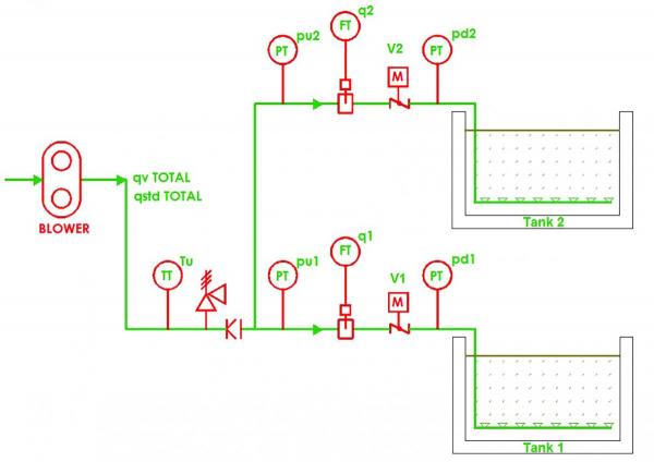
Figure 1.
If pressure drops in piping and diffusers are ignored, the downstream pressure is identical for both tanks because submergence is equal. Differences in diffuser pressure loss are negligible. The common air header creates equal upstream pressure at both tanks. Therefore the pressure drop across both valves is identical.
In systems with several tanks the valve restriction and airflow will vary from tank to tank, but the Δp will be approximately the same. This is true whether the distribution system contains two valves or twenty. It is true regardless of the type of control device being used for throttling flow.
The upstream pressure of the system is determined by the valve at the position creating the lowest pressure drop necessary to meet the required airflow. This is the “most open valve.” In automatic control systems sophisticated programming is required to establish the most open valve. For this simplified example V1 is established as the most open valve. At 1,500 scfm to Tank 1 and V1 set at 70% open the pressure drop will be 0.06 psi.
To create an airflow rate of 750 scfm at a Δp of 0.06 psig V2 must create a Cv of ≈700. With a typical BFV this is achieved at 56% open. Any control valve, regardless of type, would have the same Cv and Δp at these conditions.
It is instructive to analyze the position response of V2 when V1 is in different positions as depicted in Figure 2, which depicts valve positions in the two-tank system. As V1 is closed the pressure differential at 1,500 scfm increases. This in turn requires V2 to move further closed to create the Cv needed to maintain the desired airflow. The data shows a wide range of flow rates can be accommodated so long as the position of V1 is within a reasonable range.
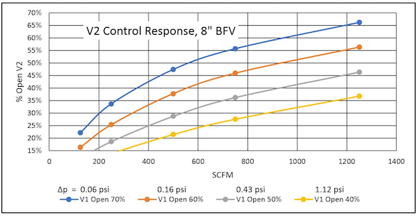
Figure 2.
The example assumes the blower is controlled to deliver the airflow required to meet the total process demand. If that’s not the case the system can go awry quickly. As the valves at the basins throttle back the system pressure rises. If pressure control or direct flow control isn’t used to reduce blower airflow the system will eventually shut down - from high pressure with Positive Displacement (PD) blowers or surge for centrifugal blowers. Control coordination between aeration systems and blowers is mandatory.
The two-valve example demonstrates the importance of Most-Open-Valve (MOV) aeration control for process performance and energy optimization. It also demonstrates that a system with properly sized BFVs can successfully control aeration systems across a wide range of process demands.
Examining Newer Valve Technologies
Economics have made BFVs the dominant throttling device in aeration control systems. In recent years newer technologies have been commercialized to provide alternate ways to control airflow. They include the iris diaphragm valve, the knife gate valve, and proprietary “jet” valves. Some designs offer integrated systems with the flow measurement device built into the control device.
The BFV has a disc mounted to a rotating shaft transverse to the flow direction. As the disc rotates it presents a changing obstruction to airflow. When completely closed a bubble tight seal is created, making it suitable for shutoff service. A variety of materials for specific application needs are available.
Another established technology being applied for airflow control is the V-Port ball valve. Instead of a disc, a ball with a through-hole is used to create a variable restriction and permit shutoff. Instead of a circular hole in the ball one side has a “V” shape to provide improved response to position changes.
Although the knife gate valve is not new technology, it is only in recent years that specialized configurations have been introduced specifically for aeration control. In operation the gate slides across the flow cross section, reducing the flow area. By using specialized shapes in the gate and seat various throttling characteristics can be obtained. The “diamond port” is common and available from multiple suppliers. Other proprietary configurations, such as an elliptical port, are available. Some knife gate valves provide a bubble tight shutoff, but many require a separate valve for shutoff.
The iris diaphragm valve gets its name from the similarity in appearance to the iris of a camera. A polygonal opening creates an orifice in the center of the pipe. By rotating the blades of the iris the area of the opening is varied, creating a variable restriction. Many iris diaphragm control valves do not provide bubble tight shutoff, and some have a limited pressure differential range.
The jet valve creates a variable annular orifice using the axial movement of a tapered control element. As the control element moves it changes the clearance between itself and the seat. This modifies the orifice area and restriction to flow. Jet valves provide bubble tight shutoff.
Integrating Aeration Blowers with Most-Open-Valve – Webinar RecordingDownload the slides and watch the recording of the FREE webcast to learn:
|
Evaluating Valve Design Performance
There are three advantages commonly claimed for alternate valve designs:
- Lower pressure drops.
- Improved control accuracy.
- Lower energy cost.
Claims of energy reduction must be tested against the Law of Conservation of Energy. The sum of the three pressures in Bernoulli’s Law, static, velocity, and friction, must always be equal throughout the flow stream, although the relative proportions may change. This sum must equal the total or stagnation pressure at the blower discharge, which equals the static pressure plus the dynamic pressure. The Δp at the most open valve dictates the value of the discharge pressure.
Comparing different valve technologies can be difficult. Claimed energy savings must be put into the appropriate context. For example, high pressure in many systems is often the result of a control strategy based on maintaining constant blower discharge pressure. If the pressure setpoint is higher than needed at the diffuser drop leg the energy wasted will be the same, regardless of control device design. Claimed reductions in pressure are often the result of implementing MOV logic to reduce total system pressure and not the result of new valve technology.
Energy savings will result if system pressure is reduced. Reductions can be approximated using the blower pressure ratio, assuming inlet temperature and air properties are unchanged:
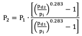
Where:
P1,2 = blower power at condition 1 and 2, kW or hp.
pi = blower inlet pressure, psia.
pd1, d2 = blower discharge pressure at condition 1 and 2, psia.
The claim that velocity head regain results in lower energy for some types is unconvincing. The dynamic pressure is negligible throughout the range of normal air velocities so potential savings are minimal. Furthermore, airflow rate is based on process demand and is independent of valve type. If size and airflow rate are identical then velocity and dynamic pressure are also identical.
Some control valves claim improved precision or greater useable travel, asserting a travel range from nearly 100 to nearly zero percent open. A comparison of Cv for various 8-inch control valves is illustrated in Figure 3 as an example. This shows that although there are variations in the Cv versus position relationship, none of the devices are entirely linear. (Note: The manufacturer of the jet valve does not publish Cv data, and therefore it is not included in this comparison.) Furthermore, in most applications the travel range is not significant; providing adequate flow control range is what is important to the process.
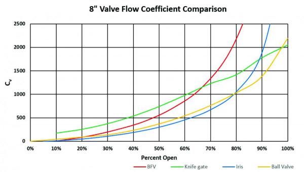
Figure 3.
Control device linearity is not critical in most systems. A Proportional-Integral-Derivative (PID) loop does perform best with linear response, but a BFV will be stable if properly sized, equipped with state-of-the-art actuators, and controlled with well-tuned loops. Furthermore, advanced control algorithms used by some suppliers often provide better accuracy and stability than PID.
BFVs can control a wide range of flow. Figure 4 illustrates a 10:1 control range for V2 in the two-valve system, provided the pressure drop through V1 is reasonable. All four valve types operate within their normal range throughout the 10:1 flow variation. Any of the four options will provide good flow control in this system.
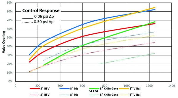
Figure 4.
In Figure 4, which was developed by analyzing the two-valve system, the flow through V1 was set to 1,500 scfm at 8.5 psig downstream pressure and 180 °F, making air velocity equal to 3,000 ft/min. V1 is the most open valve, and the V1 BFV position was set at 70%. The resulting pressure drop is 0.06 psi. The Cv for the other control devices required to create a 0.6 psi Δp was calculated at various flows. The analysis was repeated with V1 positioned to create a 0.5 psig Δp. The position versus flow rate was plotted for each device. The conclusion is that despite differences in percentage open all four types were able to provide control over a wide range of flow rates.
The claimed energy savings from increased control precision assume that errors in airflow control to an aeration zone will result in excess aeration. However, it is as likely the airflow error will cause under-aeration as often as over-aeration. Furthermore, experience has shown that with proper sizing and high-quality actuators airflow can be controlled within one or two percent with a BFV. This exceeds the requirements of most treatment processes.
There are many existing systems with poorly performing airflow control, and these failures are often blamed on the inadequacies of BFVs. In many cases, however, the failures were the result of poor sizing, unstable control algorithms, or inaccurate valve actuators.
Erratic control is often the result of poor actuator performance. Older actuators were often unable to provide position accuracy better than plus or minus 3%. Newer designs, with encoders, slow travel times, and digital communications can achieve better than plus or minus 1% accuracy.
Perhaps the most common problem in airflow control is improper sizing of the valve, regardless of type. Obviously, high air velocities through an undersized valve creates excess pressure drop, even at maximum open position. A more common problem, though, is oversizing the valve. This is usually done with the intent of minimizing frictional pressure drop. If this results in operating in the unstable (nearly closed) region small changes in position will result in large changes in Cv and pressure drop. This is true for any type of control device.
It is important to calculate control system performance across the normal operating range of the aeration system. Design specifications are usually based on worst-case conditions. Of course, the system must maintain process performance at design conditions. However, the worst case doesn’t represent normal operation, and therefore should not generally be used in analysis for energy or control optimization. Experience has shown that a system with properly sized control valves and effective MOV control will typically operate at pressures 0.5 to 1.0 psig lower than worst-case design conditions.
The Importance of Rigorous Analyses
Valves function by creating pressure drops. Valves controlling airflow provide an adjustable restriction to create the available pressure differential at the required flow rate. Pressure drops across valves in aeration system drop legs are significantly lower than the static pressure downstream of the valve and total system pressure.
In any system the pressure drop will be approximately equal for all flow control valves. The magnitude of pressure drop is determined by the most open valve – typically the valve with the highest velocity. Minimizing pressure drop and optimizing control range requires automatic Most-Open-Valve logic.
There are many types of control valves available for aeration service. Many of these represent higher initial cost than the commonly used butterfly valve. In some applications the higher cost may be justified by lower energy consumption or better control precision. However, rigorous analysis of each application based on realistic conditions should be employed to verify the higher equipment cost is justified.
Any alternative valve selection must be capable of providing the necessary level of control accuracy. The alternative with the lowest lifecycle cost, i.e. the sum of energy cost and equipment cost, is the optimum selection.
For more information contact Tom Jenkins, President, JenTech Inc., email: [email protected] or visit http://www.jentechinc.com/
To read Part 1 of these series, visit /technology/aeration-blowers/basics-aeration-control-valves-%E2%80%93-part-1.
To read similar articles on Aeration Blower Technology, please visit www.blowervacuumbestpractices.com/technology/aeration-blowers.